8 External Control Overview:
At Standard Bots, External control refers to the ability to command and monitor our collaborative robots using external devices—most commonly a PLC or a PC based system. This setup allows our robots to function as part of a larger automated cell, communicating in real-time with other equipment such as HMIs, conveyors, presses, vision systems, and safety hardware. This setup allows for seamless communication between the robot and external systems, enabling precise coordination, automated workflows, and enhanced safety tailored to our specific applications.
Why use External Controls?
- Enables operators to start or stop robot cycles directly from HMIs via a PLC
- Coordinates robot actions with other equipment in the automated cell, such as presses, conveyors, and safety devices
- Enhances system flexibility by allowing centralized control and integration
- Supports advanced decision-making by interfacing with vision systems, AI, or higher-level control logic
The steps within our External Control and what they do:
| Step |
|---|
| Initialization & Handshake |
| Robot Ready Signal |
| External Start Command |
| End-of-Cycle & Reset |
| Safety & Fault Handling |
Common External Interfaces:
Type | Typical Use Cases | Notes Digital I/O | Simple signals like Start, Stop, or Ready | Fast, reliable, low data volume Modbus TCP | Connect to PLC or HMI using industrial protocol | Widely used in automation Safety Inputs | E-stop and safety relay signals | Must be hardwired and safety rated
Example:
Scenario: A PLC or control box sends a signal to start or stop the RO1 when a part is present and safety conditions are met.
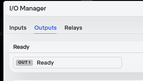
Hardware setup: DI1: Start signal DI2: Stop signal DO1: Robot ready (feedback to PLC)
Robot Configuration: Go to settings > I/O manager Assign DI1 > Start Program Assign DI2 > Stop Program
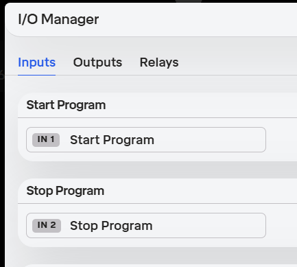
Assign DO1 > Ready
Set robot to “External Control Mode”
8.1 Configuring EtherNet/IP Communication
8.1.1 Introduction
This section explains how to configure the RO1 robot for external control via EtherNet/IP using Studio 5000 Logix Designer. The process includes enabling EtherNet/IP on the robot, installing the Electronic Data Sheet (EDS) file, adding the robot as an Ethernet device, and integrating the provided Add-On Instruction (AOI).
8.1.2 Configuration Steps
Step 1: Enable EtherNet/IP on the Robot
Connect to the robot using the web interface.
From the Main Menu (bottom-left corner), navigate to: Settings > External Control.
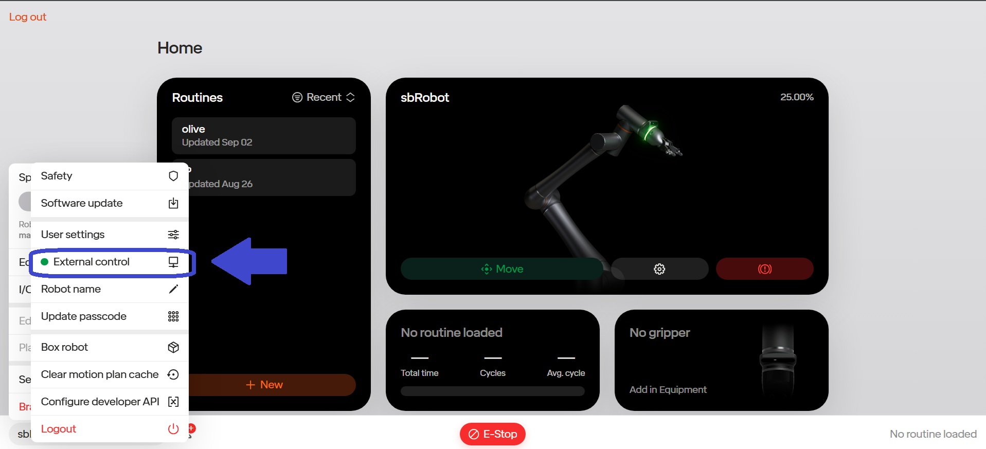
Enable External Control if it is not already active.
Toggle the EtherNet/IP Adapter switch to ON.
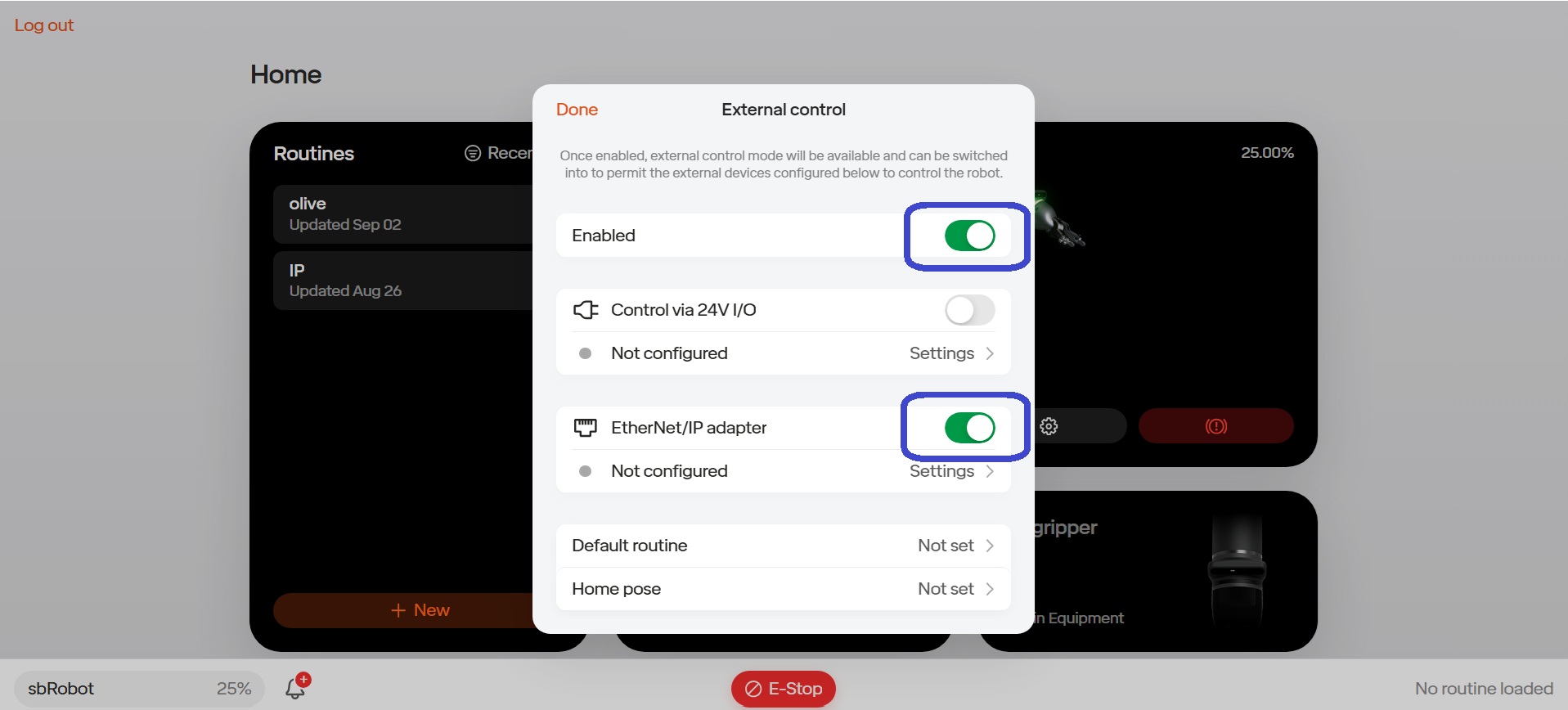
Select Settings to open the network configuration.
In the Network section:
- Enter the Host IP Address →
192.168.110.105(example). - Confirm the Port is set to
44818(default for EtherNet/IP communication).
- Enter the Host IP Address →
Click Save.
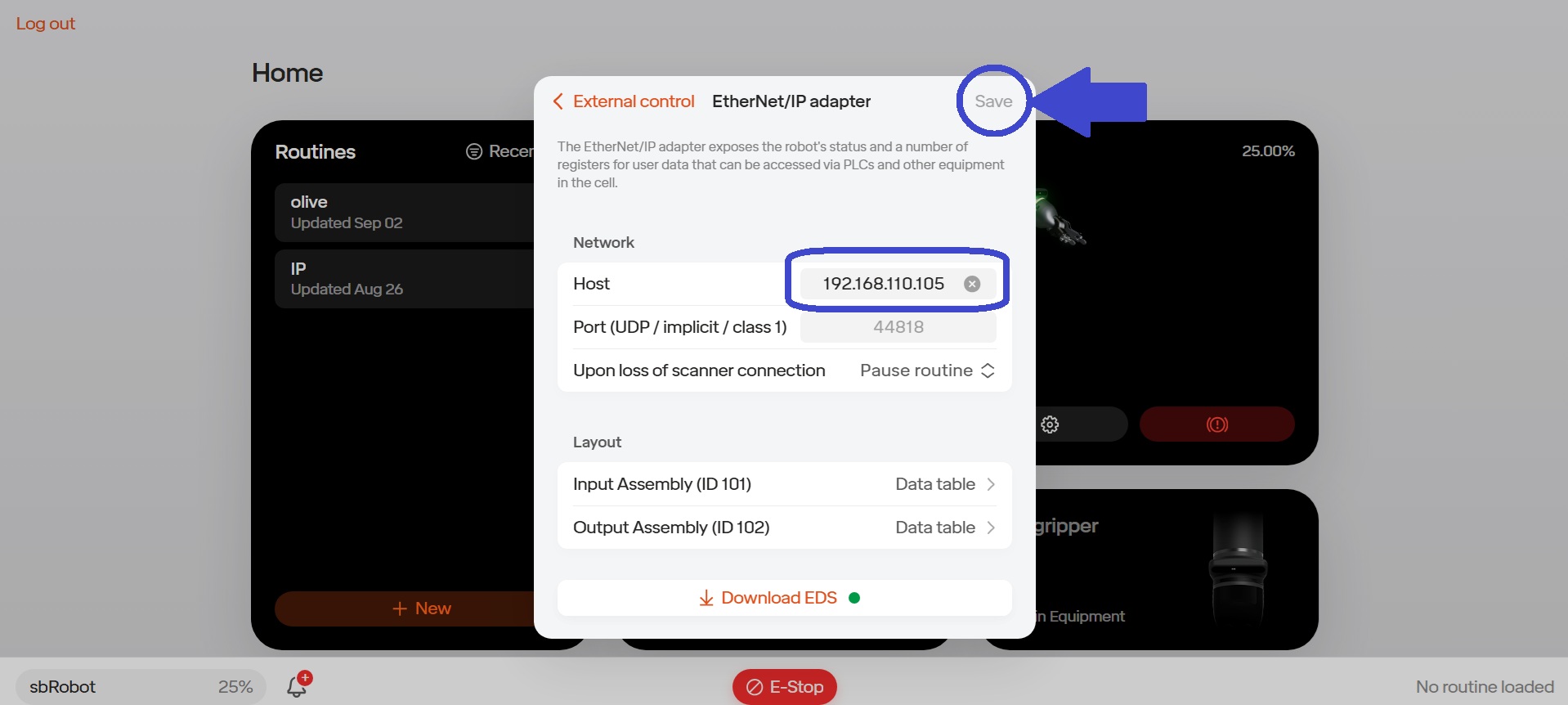
Note: At this step, you may also define variables within the input and output structure. This can be done in the Layout section located directly under the Network section.
Download the EDS file. The filename will appear similar to:
robot_eds_2025-09-12T15-06-21.eds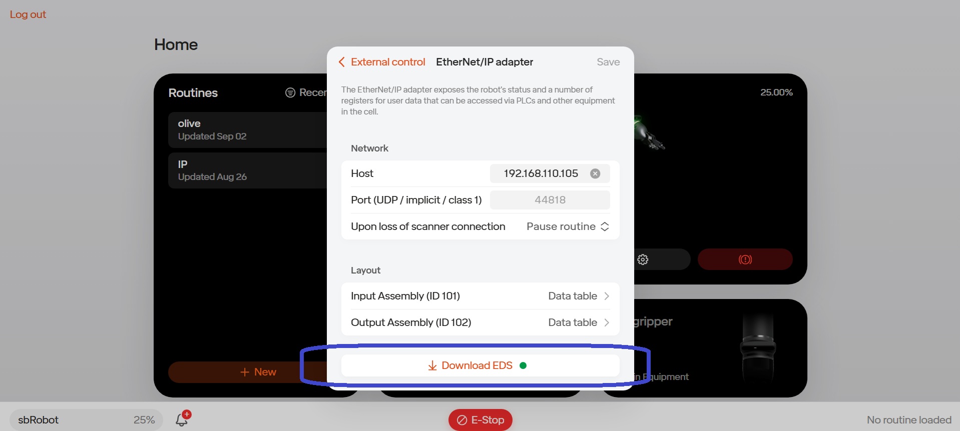
Step 2: Install the EDS File in Studio 5000
Launch Studio 5000 and open an existing project or create a new one.
From the top menu, select: Tools > Device Description Installation Tool.
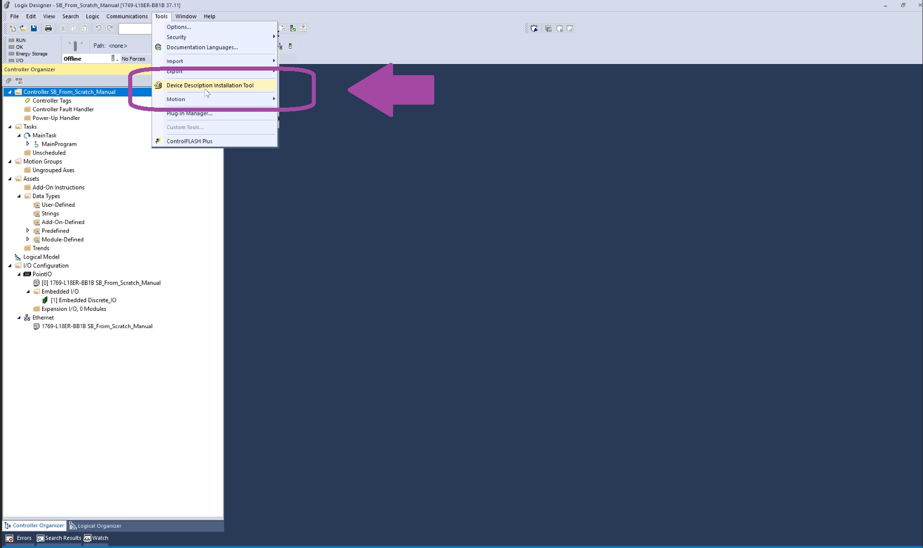
In the installation wizard:
Select Register a device description file(s) → Next.

Browse to and select the EDS file downloaded in Step 1.
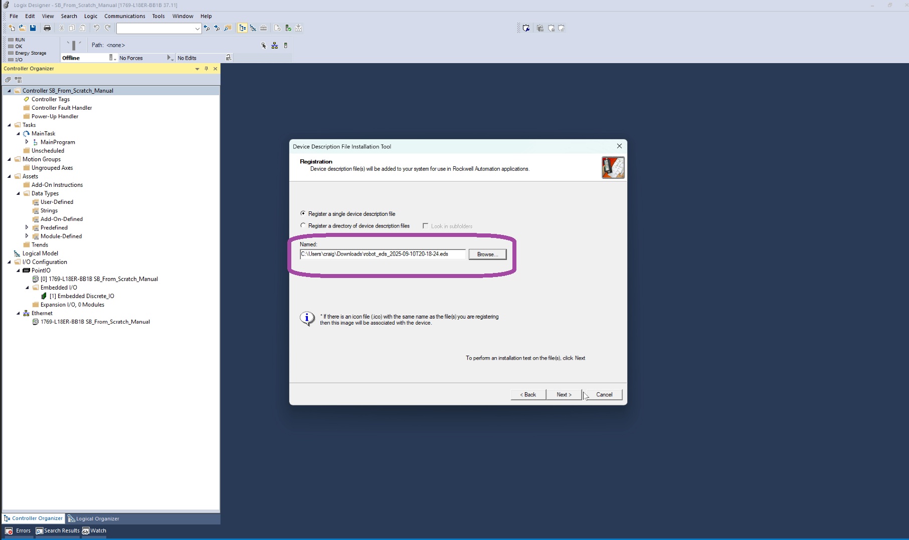
Continue clicking Next until installation is complete.
Step 3: Add the Robot as an Ethernet Module
In the Controller Organizer Tree, locate the Ethernet branch.
Right-click and select New Module.
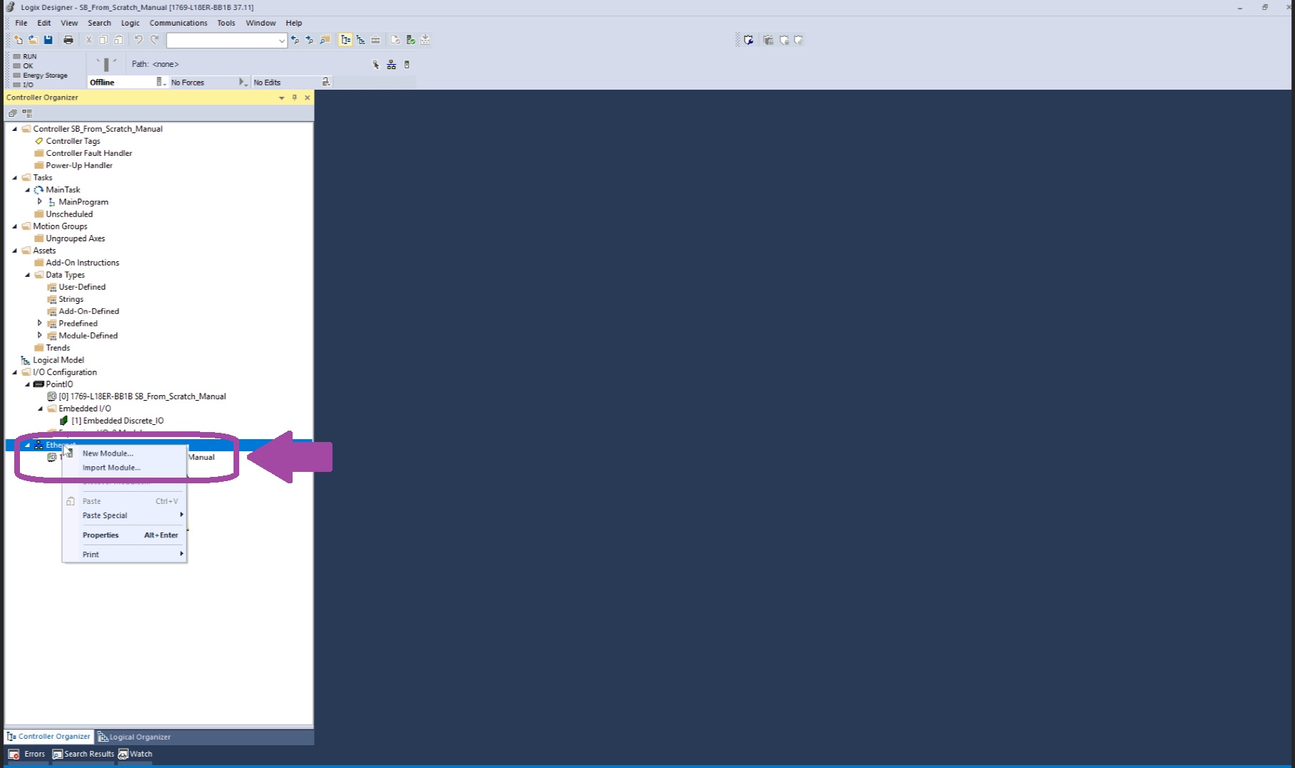
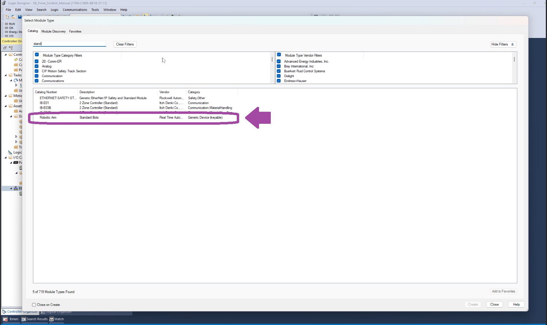
From the list, choose the Standard Bots module type.
In the configuration window:
Enter a Module Name (e.g.,
Standard_Bot).Set the IP Address →
192.168.110.105. (Note: IP address will be determined by user, 192.168.105 was used only for demo purposes.)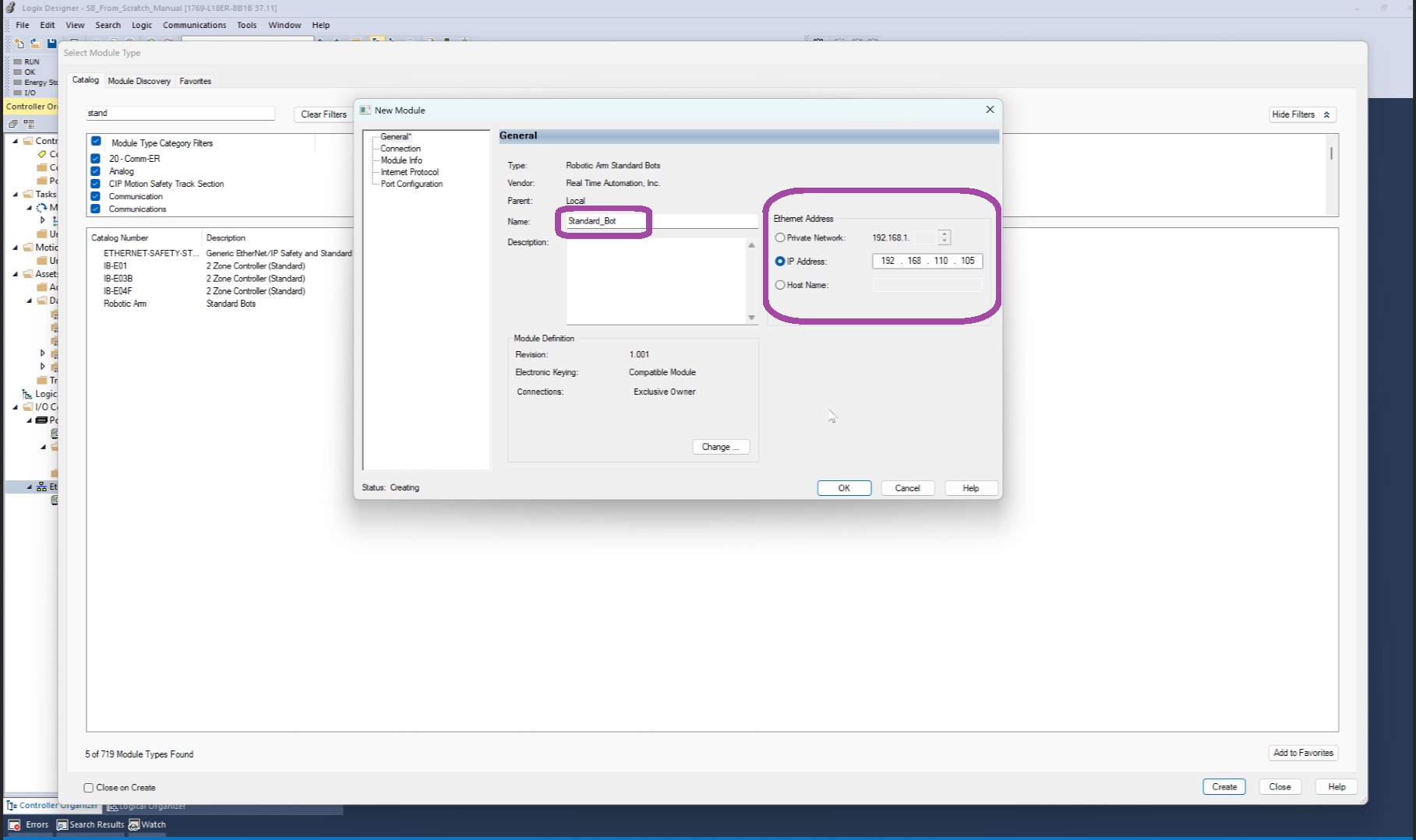
Modify the Module Definition:
Click Change.
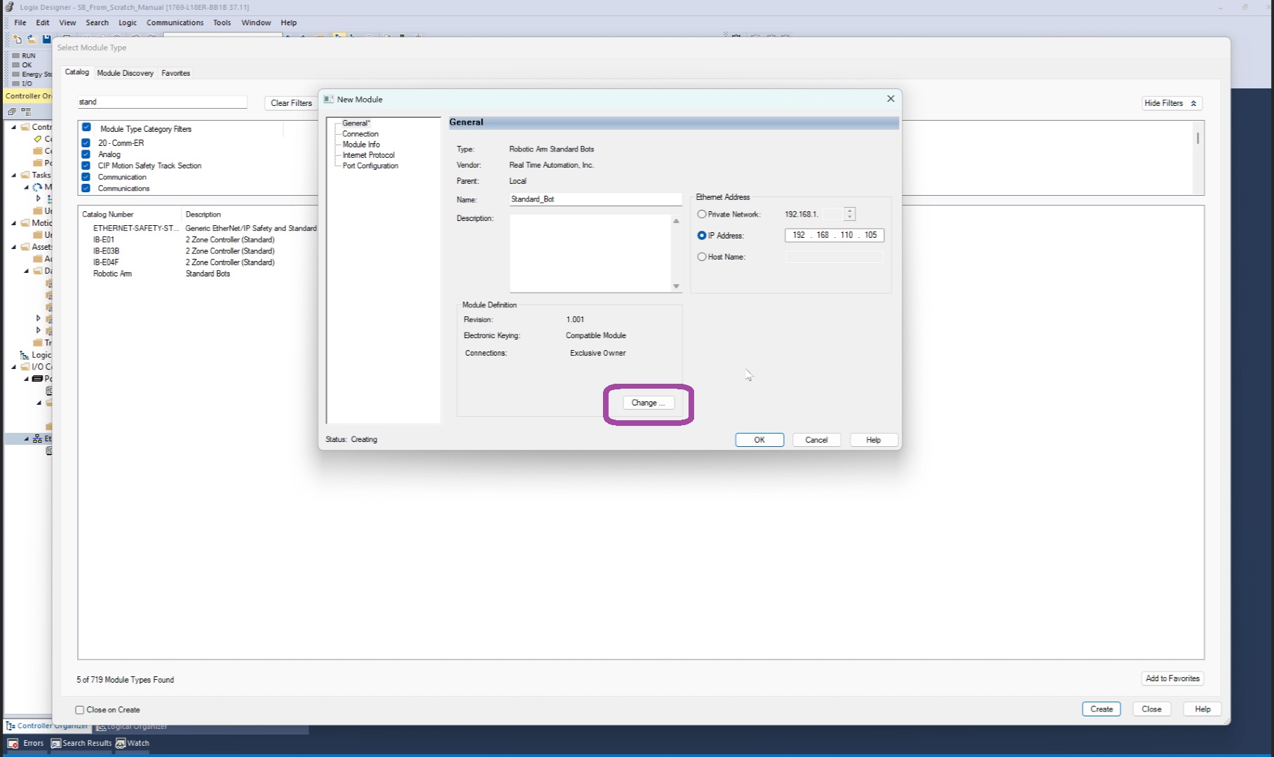
Set Electronic Keying to Disable Keying.
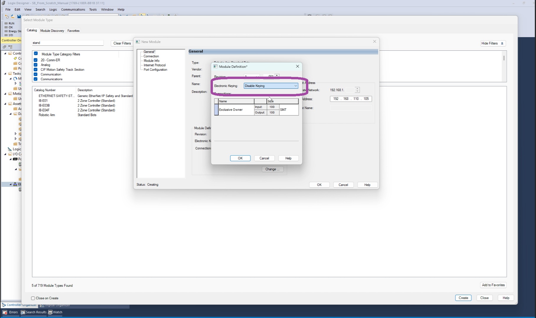
Confirm with OK, then select Close.
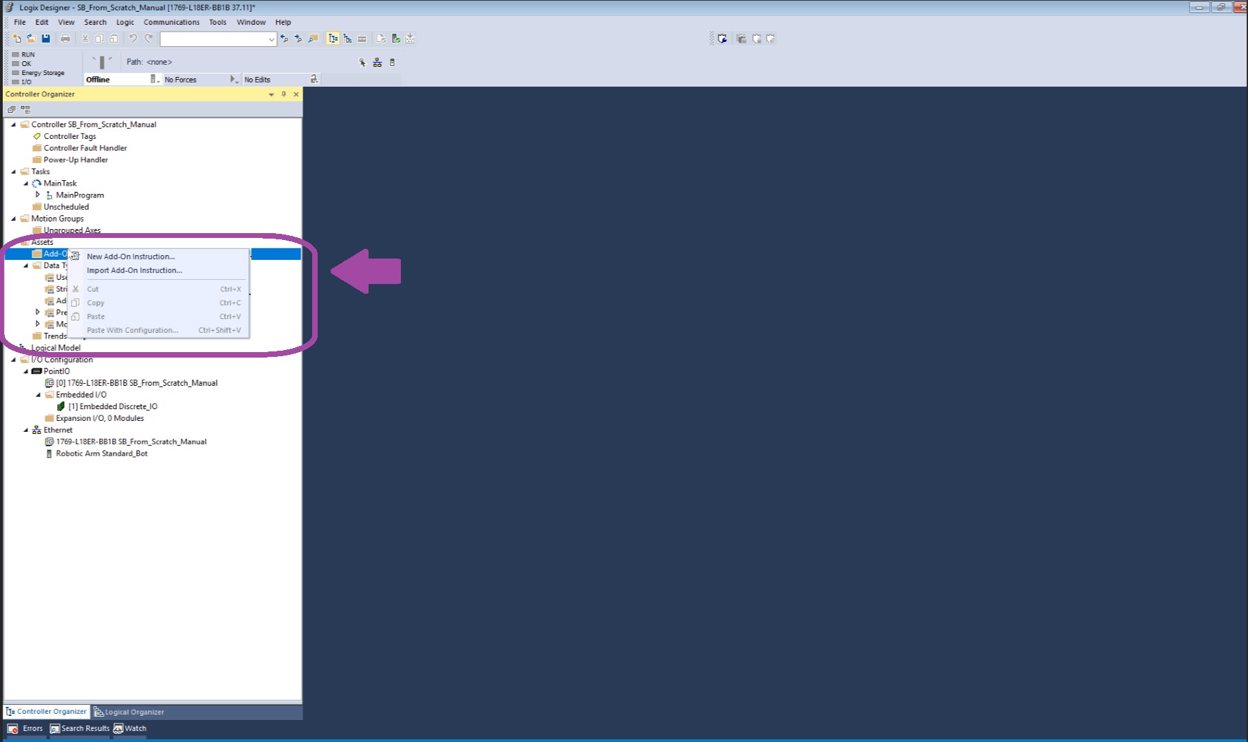
Step 4: Import the Add-On Instruction (AOI)
Note: The Add-On Instruction (AOI) is available for download at the following link: Google Drive – AOI Files
In the Controller Organizer, expand Add-On Instructions.
Right-click and select Import Add-On Instruction.
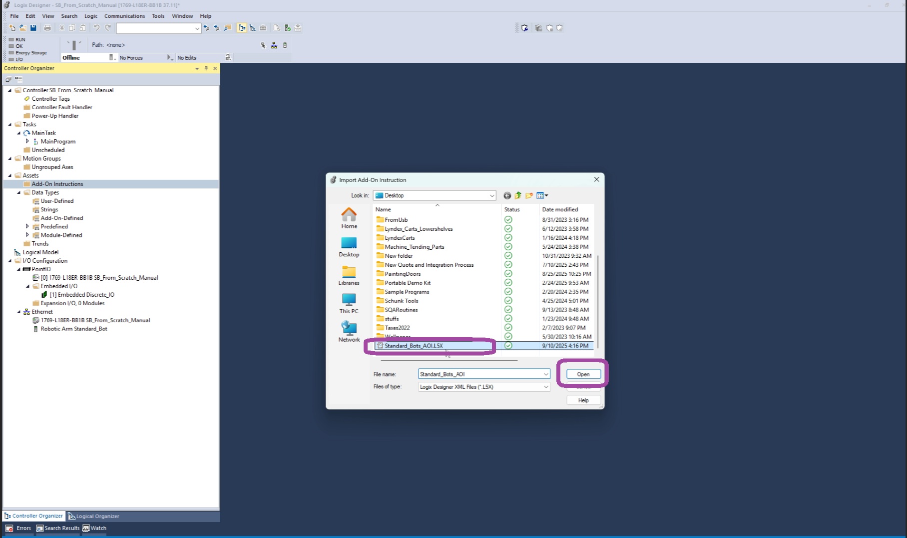
Locate and open the
Standard_Bots_AOIfile.Verify the configuration details, then click OPEN > OK.
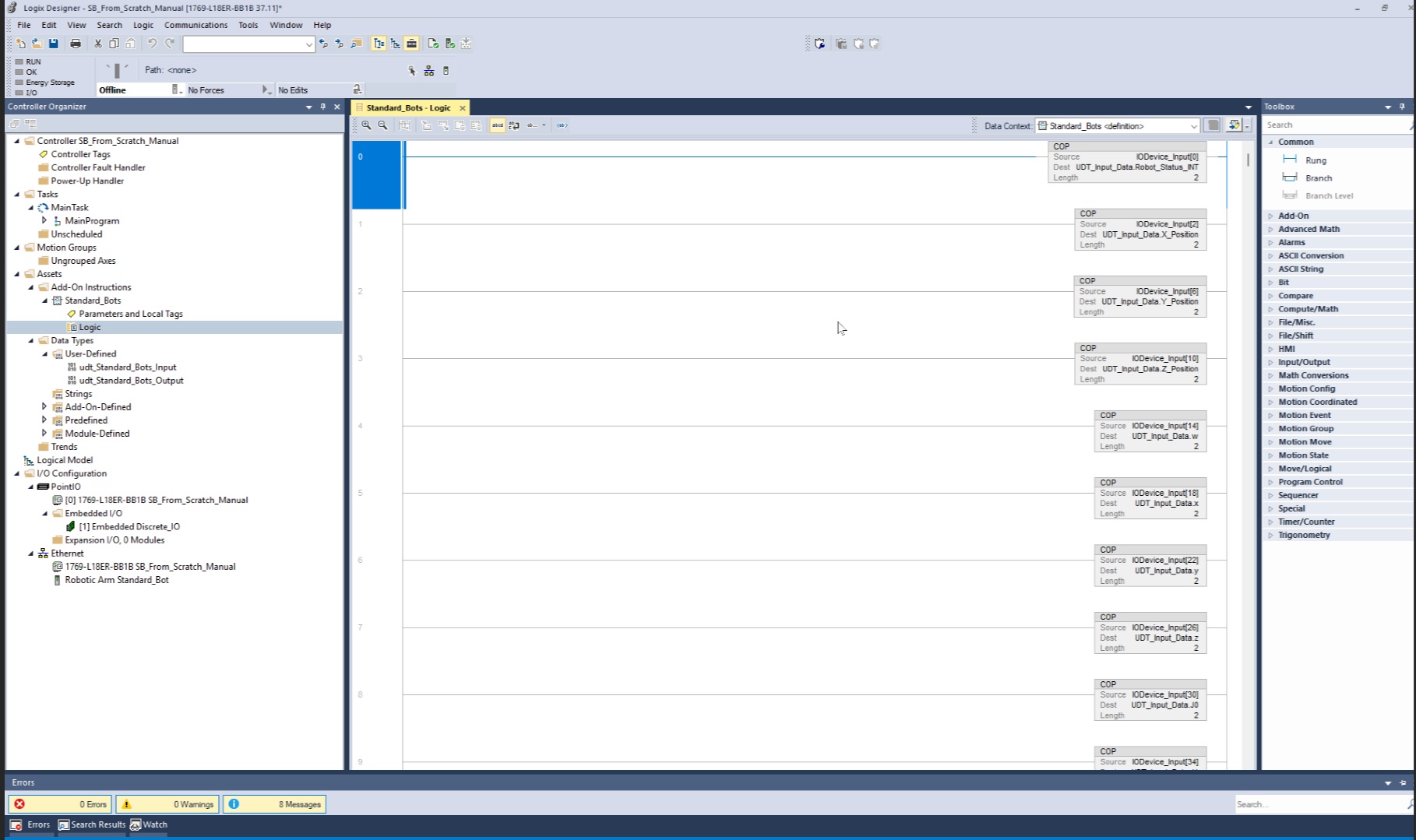
Confirm the AOI was imported successfully by reviewing its logic file in the Organizer.
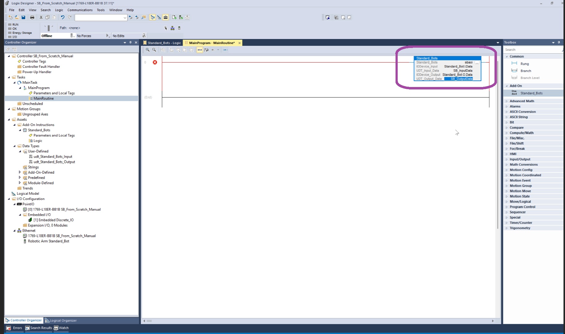
Step 5: Configure the AOI in the Main Routine
- Open the Main Routine.
- From the Toolbox > Add-Ons, drag the Standard Bot AOI into a program rung.
- Assign the following tags:
| Reference | Tag Name | Example Value |
|---|---|---|
| Standard_Bots instance | sbaoi |
Main AOI instance |
| IODevice_Input | Standard_Bot:I.Data |
Input data mapping |
| UDT_Input_Data | SB_InputData |
User-defined input struct |
| IODevice_Output | Standard_Bot:O.Data |
Output data mapping |
| UDT_Output_Data | SB_OutputData |
User-defined output struct |
Download the project to the controller .
Step 6: Verify Integration
In the MainProgram, navigate to Parameters and Local Tags.
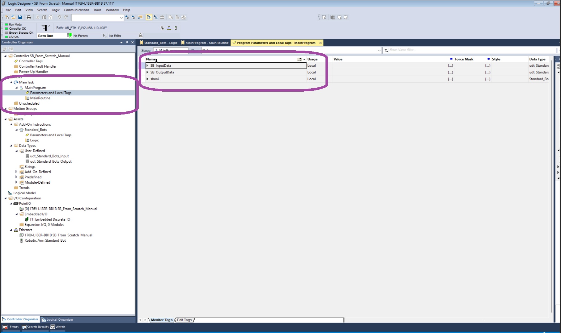
Expand the
SB_InputDatastructure.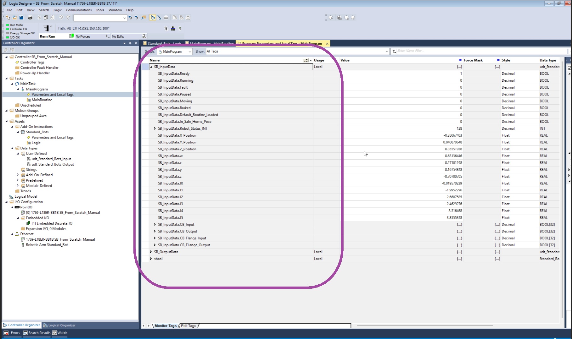
Confirm that all available robot control methods are accessible.
Conclusion
After completing these steps, the RO1 robot is fully configured for external control via EtherNet/IP in Studio 5000 Logix Designer. The AOI provides structured access to robot control functions, ensuring smooth integration with the PLC program.