6 Vision
Note: Vision is an optional paid feature. If you are interested in incorporating this into your robot, please contact Standard Bots for further assistance.
• Email: [email protected]
• Phone: 1-888-9-ROBOTS
6.1 Locate
6.1.1 Use Cases
Standard Bots Locate feature is designed to locate items on a 2D flat plane to allow for picking and placing them using the integrated wrist camera. Items to be picked do not need to be organized but must be distinguishable from each other. Locate is not designed for 3D applications (stacked items). 3D functionality will be an optional upgrade provided at a later date. Locate accuracy is dependent on how far the robot is from the plane, but at closer distances +/- 1/8 in is possible depending on lighting and calibration.
6.1.2 Setup
6.1.2.1 Required Items
- Robot with Camera
- USB Cable connected between robot and camera. Cable will be located
inside the control box from the factory.
- Calibration spike (Provided by Standard Bots or custom)
- Vision calibration grid: http://camera-calibration.standardbots.com/
- Accuracy Calibration Grid (Optional): http://accuracy-calibration.standardbots.com/
- Flat plane to pick from
- Items to pick
- Tooling to pick items
6.1.2.2 Camera Setup
- Go to the Move Robot view, check to make sure that you are Live Robot mode not Simulation mode.
- If needed, unbrake the robot.
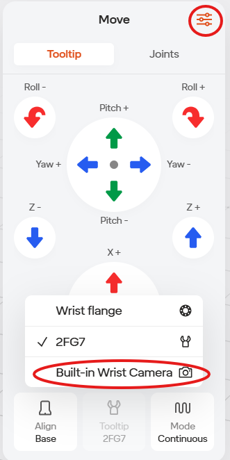
- Select the three dots icon in the upper right, then select the camera icon. If you do not have this icon, contact Standard Bots Support.
- You should see the camera view. If you cannot. Ensure the provided USB cable is connected between the robot and control box. If it is, try rotating the orientation of the usb-c plug 180 degrees in the robot.
- Go to “Equipment” in the robot menu (Menu has the robot name in it and is located in the lower left of the screen).
- Click the “+” icon in the upper right of the window.
- Add the Built-in Wrist Camera.
- You do not need to perform any calibration here.
- Click save in the upper right of the window.
- Click done in the upper left of the window.
6.1.2.3 Calibration Spike Setup
Go to the Move Robot view (located in the upper right of the screen).
Go to “Equipment” in the robot menu (Menu has the robot name in it).
Click the “+” icon in the upper right of the window.
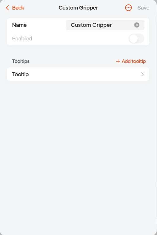
Select “Custom Gripper”.
Select “Tooltip”.
If using the Standard Bots provided spike, set the z height to 50mm. If using another spike, set the offsets accordingly.
Click save in the upper right.
Click save again in the upper right.
6.1.2.4 Space Setup
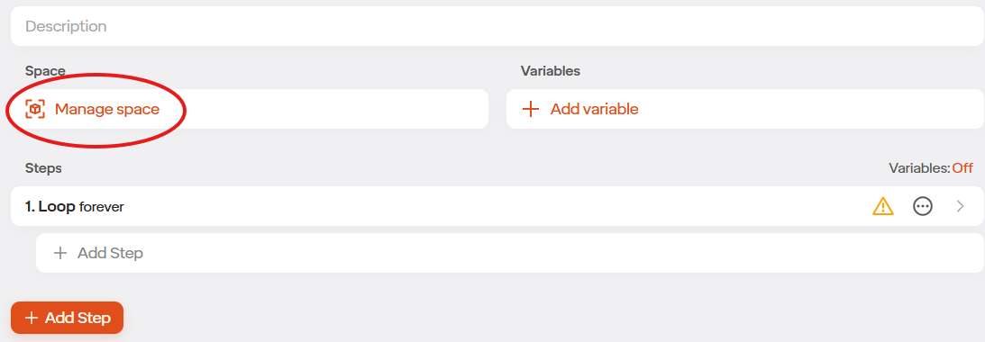
Create a new routine, or open the routine you want to run locate in.
Select “Manage Space”.
Go to “Space” in the Move Robot view (square icon located in the upper right of the screen).
Click the “+” icon in the upper right of the “Space” window in on the right side of the User Interface.
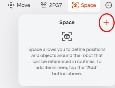
Select “Plane” in the list that appears. If you do not have this option contact Standard Bots Support.
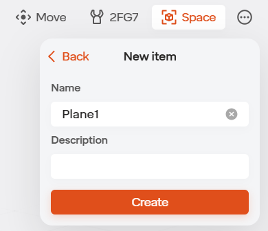
Name the plane and select “Create”.
Select “Create with Camera” and then select “Capture”.
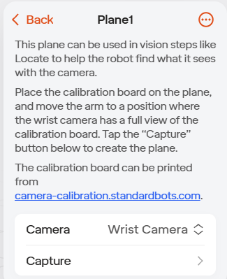
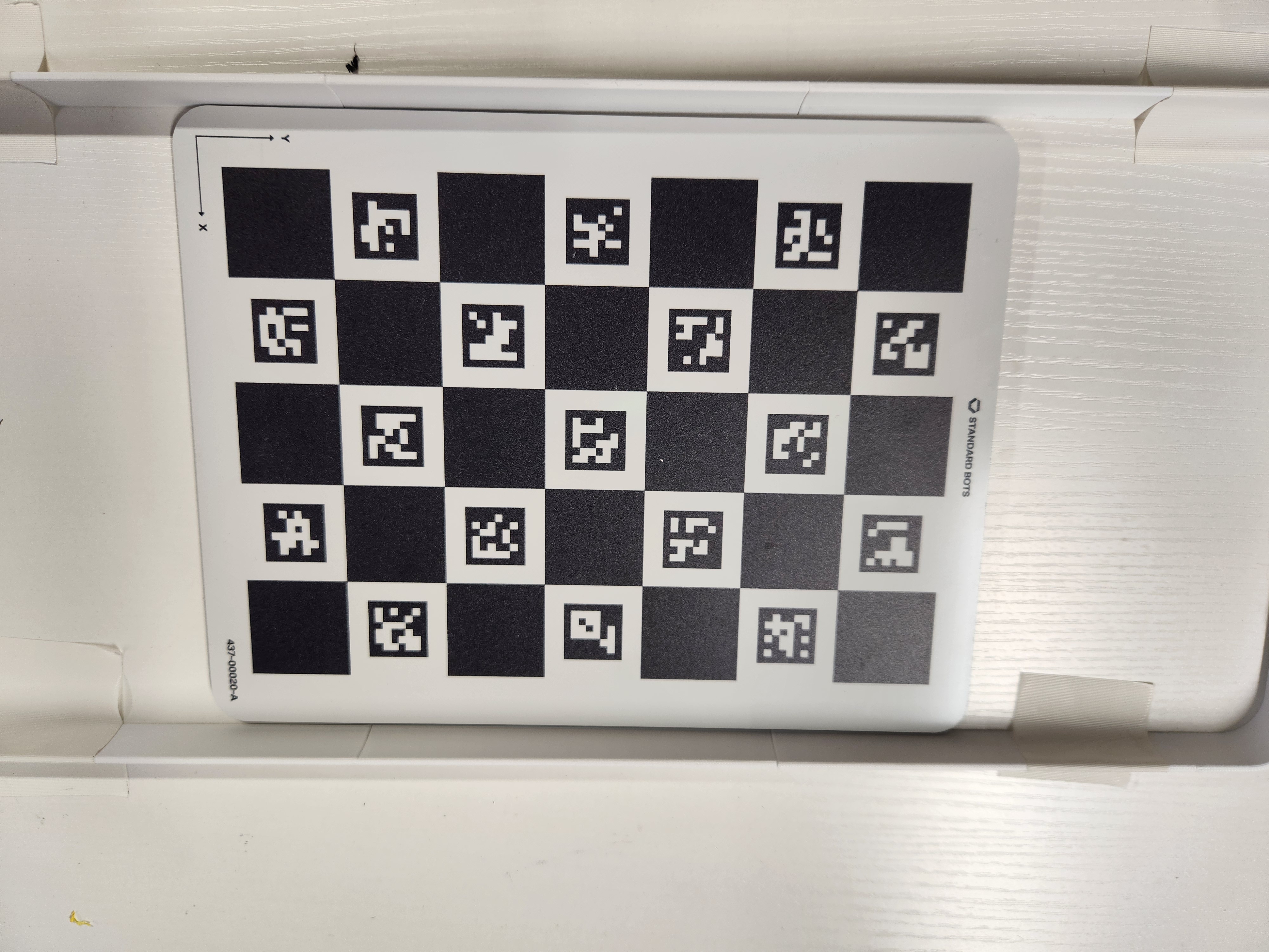
Place the larger, full 8.5 x 11 size calibration board on your plane.
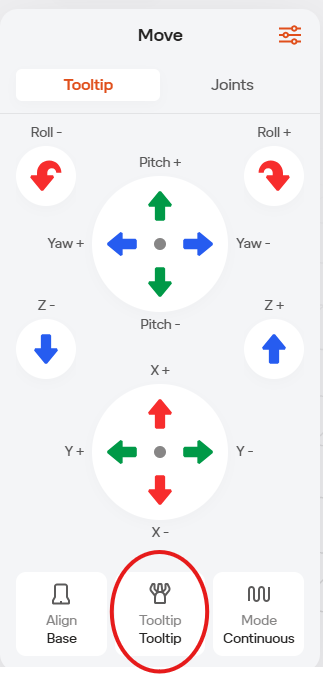
In the “Tooltip” jogging view, ensure the calibration spike custom tooltip is the current tooltip.
Drive the robot so you can see the calibration board with the camera. You can see the camera view while jogging by selecting the camera icon. Ensure the joint positions make sense and don’t appear at risk of hitting your plane.
Under “Tooltip” jogging you can select the “Wrist Camera” frame. You can then select the slider Icon in the top right of the tooltip jogging view. Using “Snap to Axis” you can align the wrist camera to the robot base.
Once you have the calibration grid in view, get the robot as close to it as possible while still seeing the whole grid.
Go back to the “Space” in the bottom right.
Select “Create with camera”.
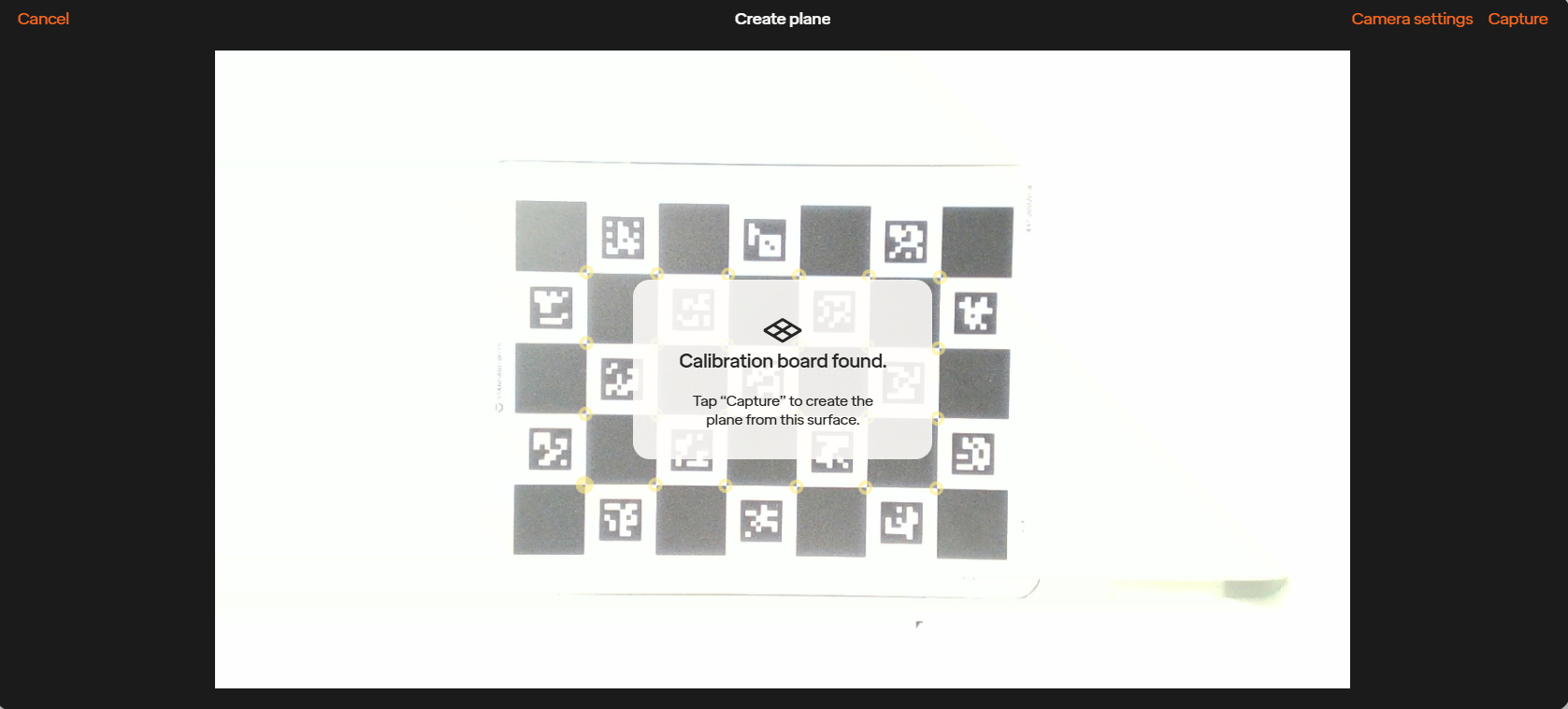
Select “Capture” in the upper right of the window. If capture is greyed out ensure you can see the whole grid, it is the correct grid and the lighting is good enough. “Calibration Board Found” will appear on the screen.
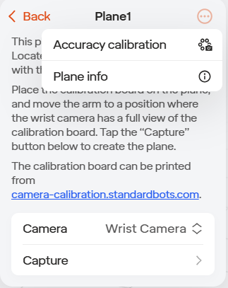
Click the 3 dot menu in the upper right of the plane calibration view.
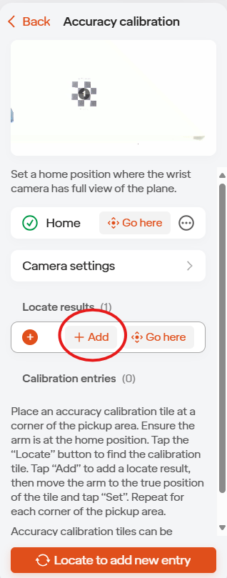
Select Accuracy Calibration.
Jog the robot so you can see the whole work area. Ensure you have your custom tooltip selected in the bottom right of the tooltip jogging view.
Go back to the plane setup in the space view .
Click “Set” to create your home position in the plane view in space.
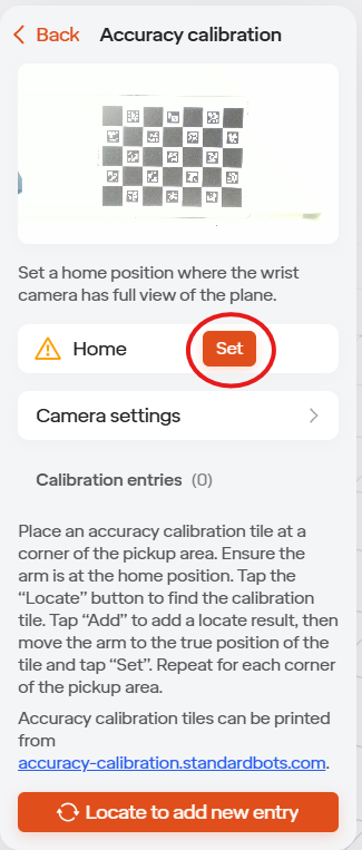
Place one of the smaller checkerboard calibration images in the robot view.
Select “locate to add new entry”.
Add the entry. Ensure you do this before navigating away from the space window to jog.
Hold down “Go Here”. Robot will drive above the grid.
Jog the robot to the center of the grid with the point of the spike touching the center. You can do this via the UI or with Anti-Gravity. Ensure the grid does not move. It is best to do this with the robot going at a slow speed.
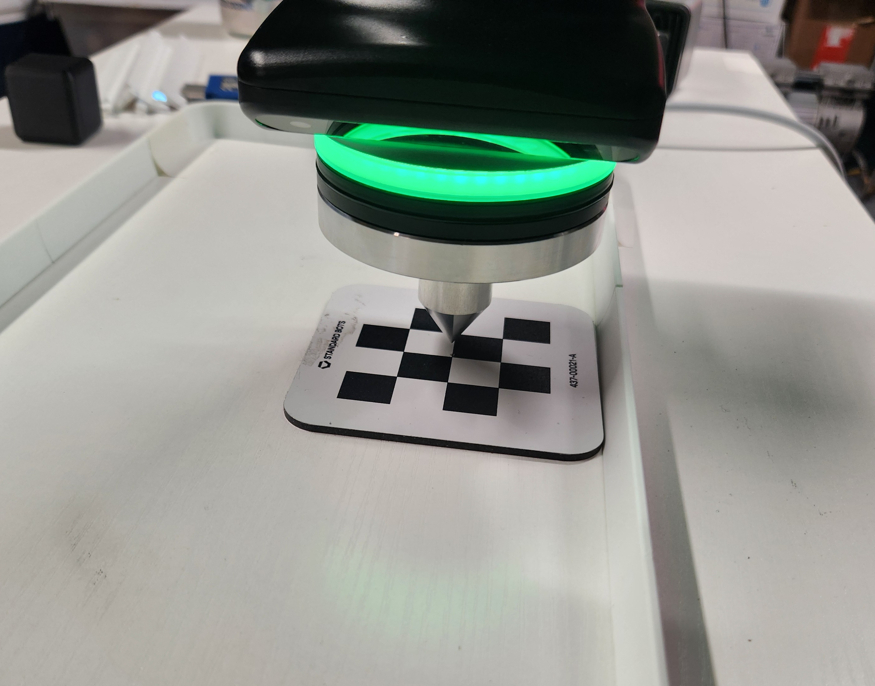
Go to the Space window again, and click “Set” for this position.
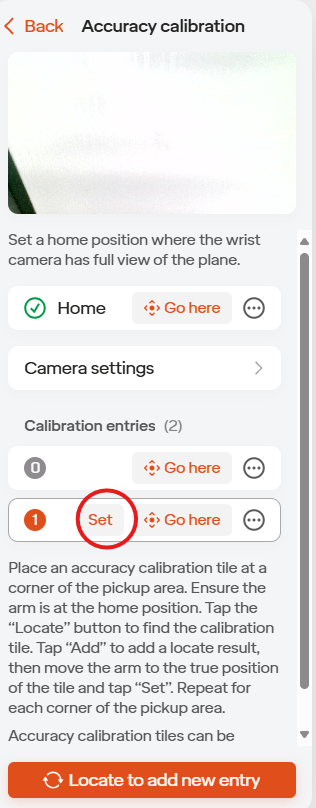
Bring the robot view back to the home position an repeat at least 4 times around your work area.
The plane is now ready to use in a Locate step.
6.1.2.5 Routine Setup
Setup a tooltip or select a standard tool under equipment manager to use in your routine.
Go to the routine you created your plane in.
Leave the existing main loop and add all the below steps in this main loop.
Setup a Move To Position positioned such that the camera can see the work area.
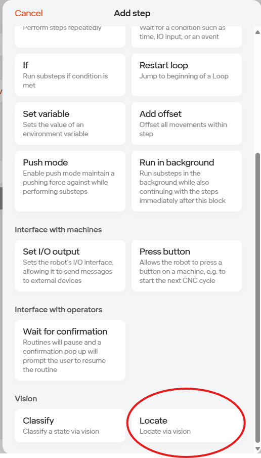
Add a Locate step (found at the bottom of the “Add Step” window.
Under the Setup tab of the locate step, set a region of interest. This is the area you want to pick from.
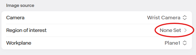
Under workplane, select the plane created in previous steps.
If needed adjust the camera settings so the items are visible. Generally the defaults are a good starting point.
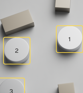
Under the Train tab (located at the top of the Locate window), setup your blob or shape settings.
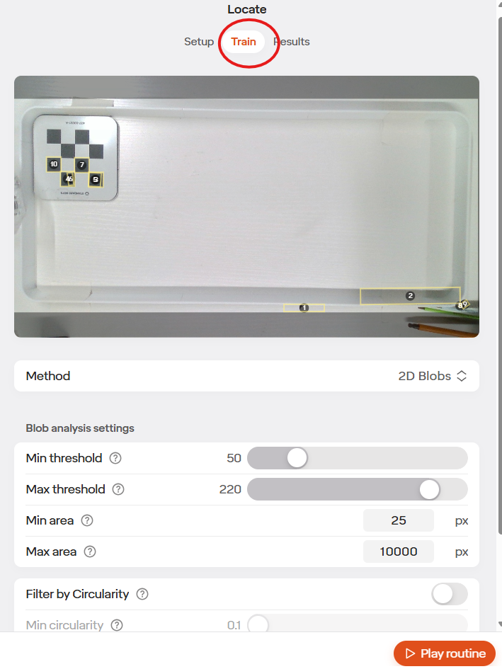
If using blobs, adjust the 0-255 Min and Max threshold greyscale value and Min and Max area values until just the items you wish to pick are indicated in the above image.
If using Shapes, Teach the image by taking an image and highlighting the items you wish to pick. Set the bounding box around the item. Adjust the % match required until all items you wish to pick are indicated in the above image.
Under results (located to the right of the Train tab), if needed limit the number of items locate should find.
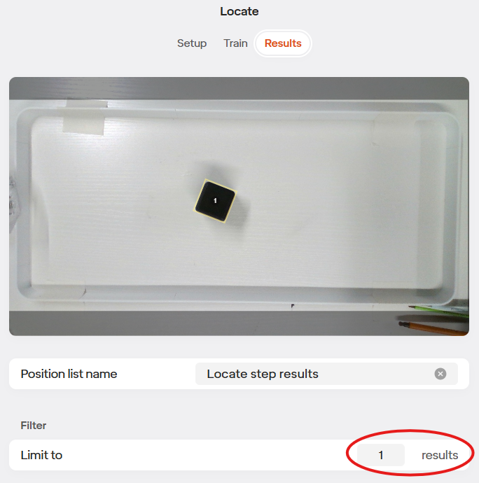
If needed, in results set a transform to apply to the located position when the robot goes to pick. Generally, it is good to start with a larger z offset of 40mm or so and tune from there.
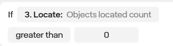
Add an if statement below the locate step.
Set the if statement to say “IF Objects located count greater than 0”. Objects located count is automatically created for you when you add a locate step. This will ensure the robot only tried to pick if there are items to pick.
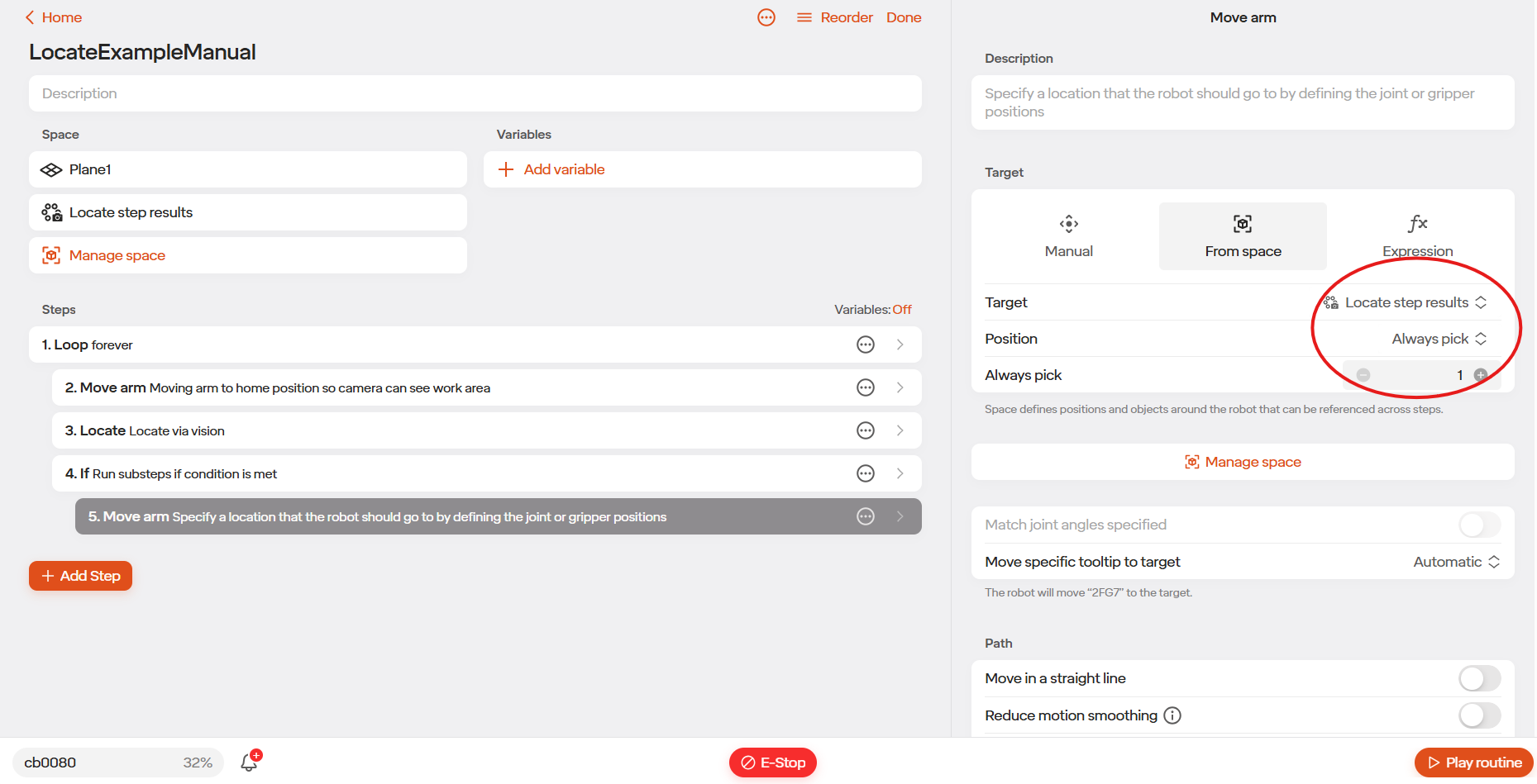
Add a Move Arm.
Select “From space” in the Move Arm command. Select “Locate Step Results”. Set it to always pick 1. This will pick the first item in the locate step results list.
Fill out the rest of the routine as desired. You likely will want to do an add offset to to the locate results item before driving to it, etc.
6.2 Classify
6.2.1 Use Cases
Standard Bots Classify feature is designed to allow the robot to look at an item and determine it’s state by comparing the current view to reference images. Classify can be used to look at a light stack to determine the machine state or to look at a HMI screen to know when a program is finished. Classify is not suited for detailed inspection / metrology applications.
6.2.2 Setup
6.2.2.1 Required Items
- Robot with Camera
- USB Cable connected between robot and camera. Cable will be located inside the control box from the factory.
6.2.2.2 Camera Setup
- Go to the Move Robot view, make sure the Robot view is in Live view and not Simulation.
- If needed, unbrake the robot.
- Select the three dots icon in the upper right, then select the camera icon. If you do not have this icon, contact Standard Bots Support.
- You should see the camera view. If you cannot. Ensure the provided USB cable is connected between the robot and control box. If it is, try rotating the orientation of the usb-c plug 180 degrees in the robot.
- Go to “Equipment” in the robot menu (Menu has the robot name in it, located in the lower left of the screen).
- Click the “+” icon in the upper right of the window.
- Add the Built-in Wrist Camera.
- You do not need to perform any calibration here.
- Click save in the upper right of the window.
- Click done in the upper left of the window.
6.2.2.3 Routine Setup
Create a new routine, or open the routine you want to run classify in.
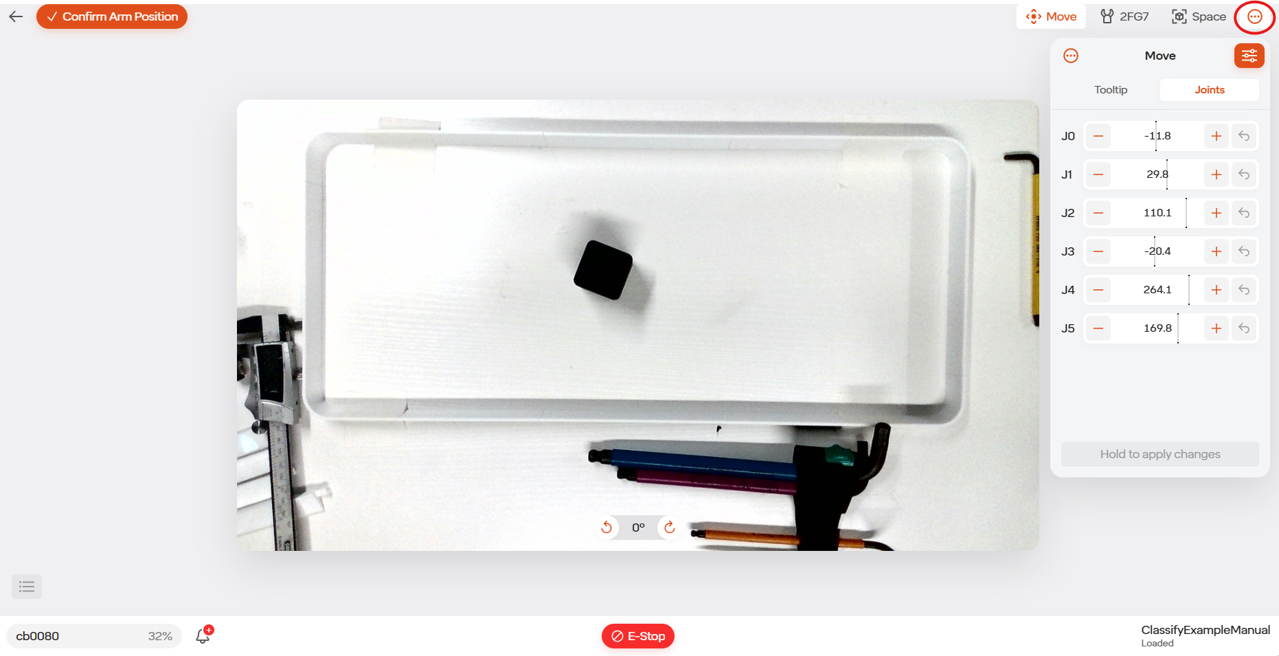
Add a “Move Arm” step and set the position such that the camera can see the item you want to determine the state of. You can see the camera view while jogging by selecting three dots icon located in the upper right, then by selecting the camera icon.
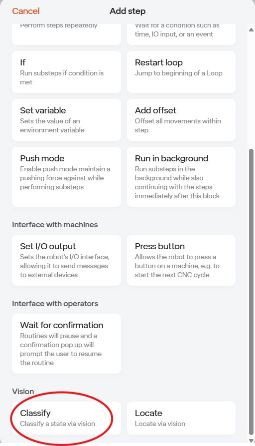
Add a “Classify” step (located at the bottom of the Add Step Window).
Under “Setup” set the Region of interest to be only the part of the screen that is going to change state. Move the box outline and when done select “Crop”.
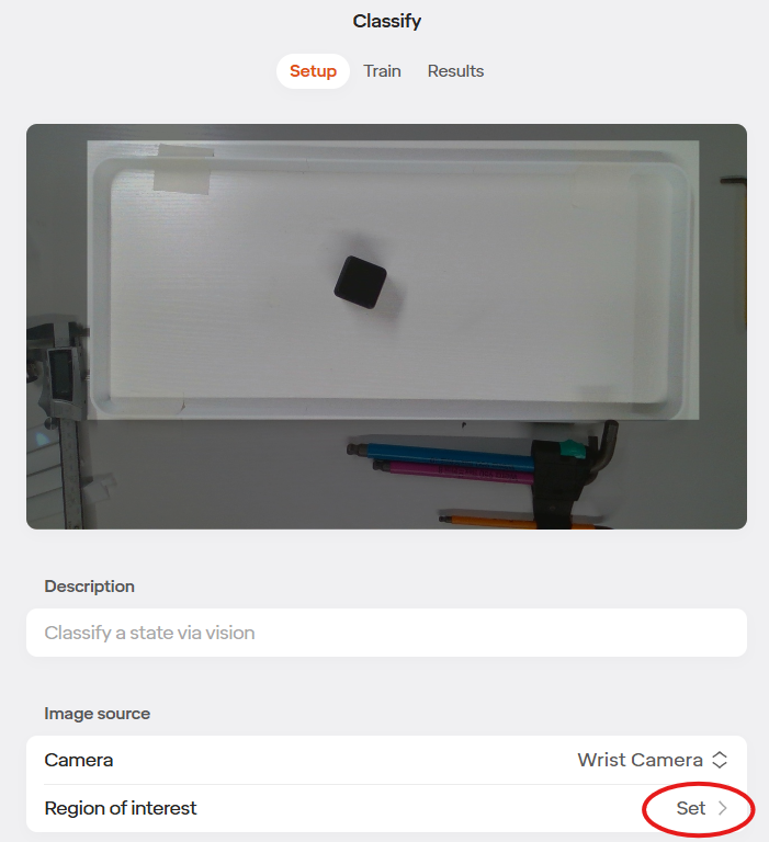
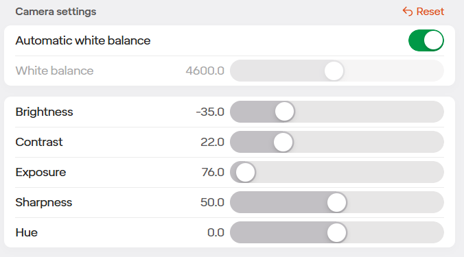
You can adjust camera settings if needed, but the defaults work for most applications.
Under “Train” in the Classify step (located at the top of the Classify window), Capture a new class for each state and provide it a name.
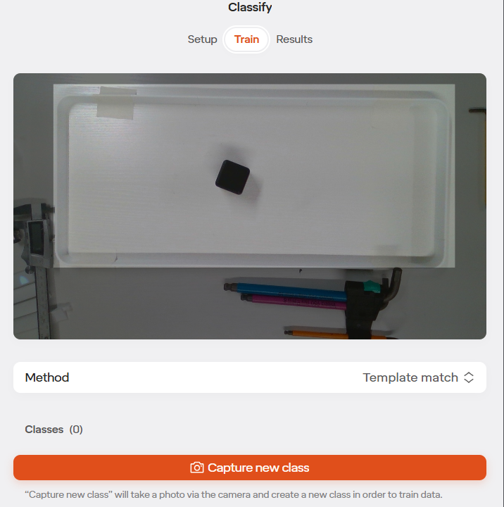
If desired, add a fallback class to default to if no state is matched.
Under “Results” (located at the top of the Classify window), test the different states to see if the right result is reported. Adjust the minimum match threshold as needed.
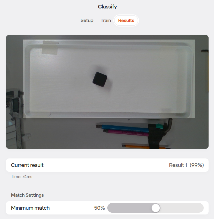
Add an IF statement below the Classify step. You can now adjust the IF to say “IF Classify Results is (State programmed in Classify)”.
Create the rest of the program as desired.