5 Software Overview
5.1 Connecting to the Robot
5.1.1 Connecting Via iPad
The included iPad can be connected to multiple RO1 robots (if needed) after pairing with them.
The home screen of the Standard Bots app shows the list of paired robots and their connection status. Tapping on the “…” button for a robot allows you to: * delete that robot * re-configure it (i.e. to change its network settings, PIN, etc) * show a details screen that can allow you to troubleshoot connectivity issues.
If a robot is powered on but not showing up here, after confirming the tablet is on the same network, check its details and contact customer support.
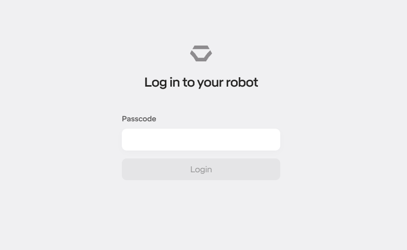
To connect to your robot, enter your PIN to log in. The default PIN is 0000:
5.1.2 Network Settings Page
To change the Network settings for the robot, you can do this directly using a web browser without having to use the iPad App. You can change the settings directly via the Network Settings Page. If you use a USB-C network adapter connected to your iPad see 12 Appendix C: How to direct wire robot.
To change the network settings, open up a web browser and connect to your robot. If you are already logged in, click Log Out at the top. Then click “Configure Network” below the Login button.
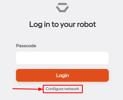
You will be asked for your passcode.
The Network Setup page will then look like this:
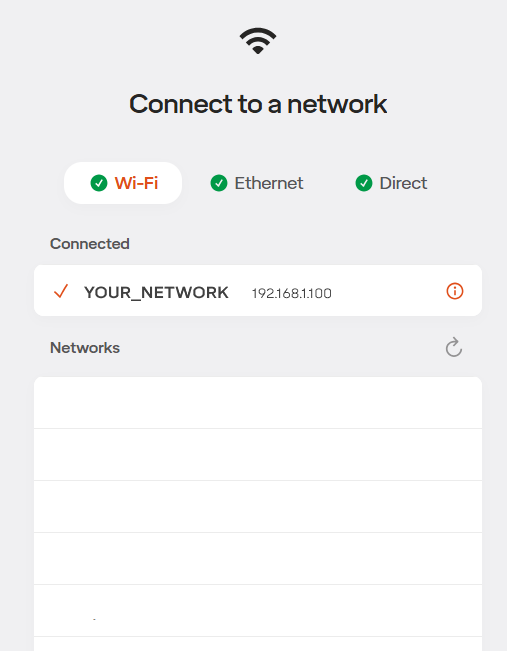
To enable any network check the checkbox beside it.
Wi-Fi - this is recommended to be your company’s Wi-Fi network so that the robot can be connected to program PCs etc.
Ethernet - this is the RJ45 port on the bottom of the Control Box and is usually the machine network
Direct - this is the USB-C connection on the bottom of the Control Box
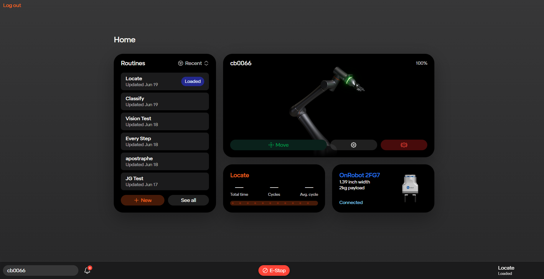
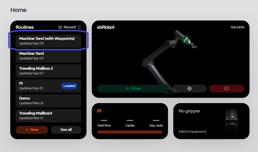
5.1.3 Home Page
The Home Page shows the routines, the current robot, and the end effector that is connected to the robot. In the “routines” tab, you are able to load, edit, and create new routines for the robot. In the tab that shows the connected robot, this is where you can go to move the robot.
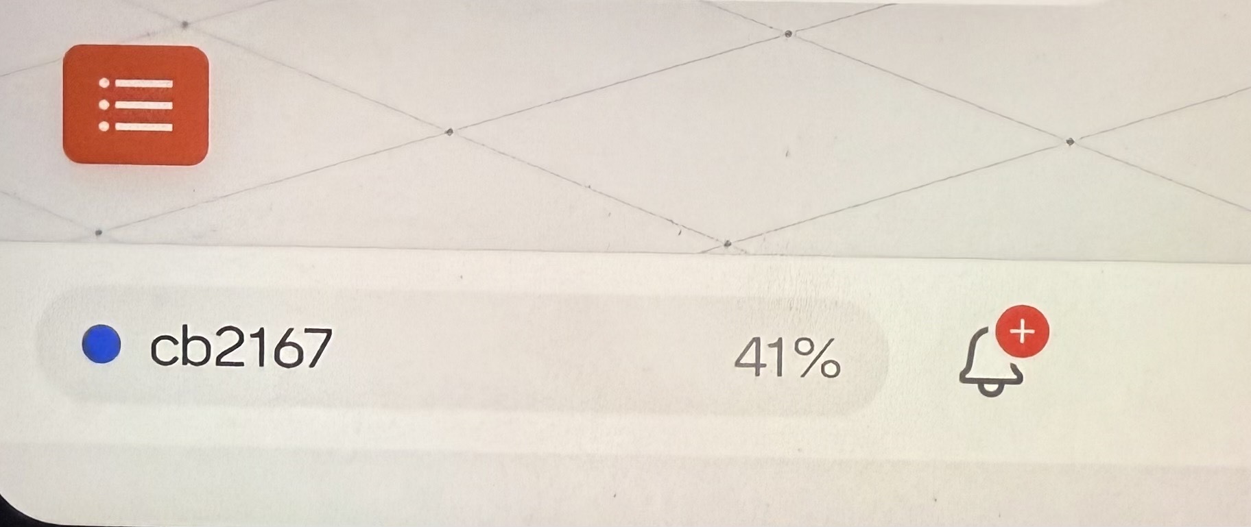
5.1.4 Footer
Once connected to an RO1, the software has a set of global controls in the footer of every page:

There are several important features worth calling out:
| Element | Name | Description |
|---|---|---|
| Notifications | Contains a log of failures, errors, and other notifications that have occurred when running the robot. If there are unread items here, there will be a red dot on this icon. | |
| E-Stop | Trigger an emergency stop and brake the robot. | |
| Robot Menu | See status of current robot and access settings (see below). | |
| Loaded Routine | Shows what routine is loaded onto the robot. |
5.1.4.1 Robot Statuses
The robot menu displays the name of the robot and may show several status indicators:
| Status | Description |
|---|---|
| DISCONNECTED | The tablet is not able to connect to the robot. |
| LOADING | The tablet is trying to connect to the robot. |
| MOVING | The robot is being manually jogged now. |
| ANTI-GRAVITY | The robot is being moved in Anti-Gravity (hand-guided) mode. |
| RECOVERING | The robot has exceeded joint limits and can be moved back within limits now. |
| RUNNING | The robot is running a routine. |
| PAUSED | The robot is paused in a previously-running routine. You can press ‘Play’ to resume it. |
| E-STOP | The robot is in Emergency Stop mode. Reset the E-Stop button on the control box and any external E-stop buttons. |
| BRAKED | The robot is braked (either from having manually braked it or from a previous E-Stop). It can be unbraked in the Move screen. |
| FAILED | The robot has encountered a collision or has been affected by some other hardware issue. |
| (blue dot) | A software update is available. Check “Software Update” under “Settings”. |
| INSTALLING | The robot is installing a software update. |
5.2 Jogging the Robot
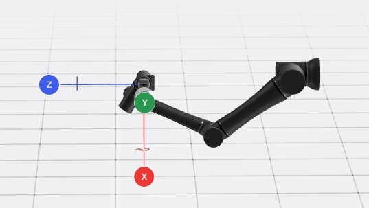
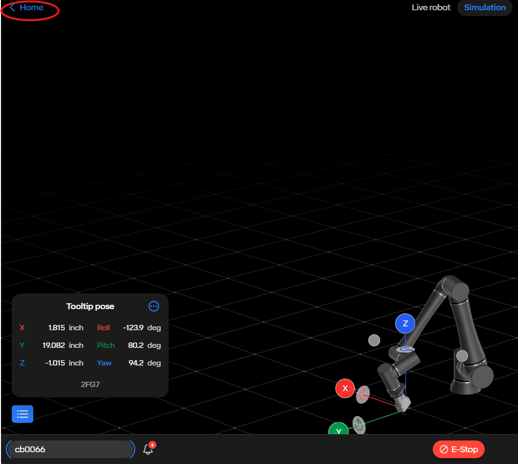
The “Move Robot” tab brings you into the Move page.
This shows a visualization of the RO1. The switch on the top allows you to switch between visualizing (and controlling) the real robot or a simulated robot.
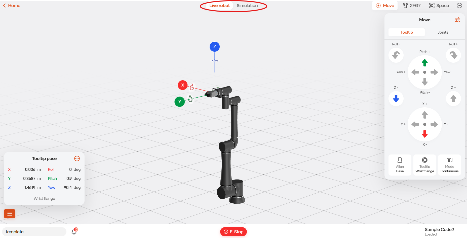
At the right of this screen are several useful tabs:
| Icon | Tab Name | Description |
|---|---|---|
| Move | Menu to access the “Joints” and “Tooltip” Tabs | |
| Joints | Controls position of individual joints. | |
| Gripper | Controls any connected gripper | |
| Space | Allows defining points and grids that can be referenced in the routine | |
| I/O | Shows the status of the I/O ports and allows manually toggling them. Hidden behind the three dots icon. | |
| Tooltip | Jogs the robot’s tooltip in Cartesian space |
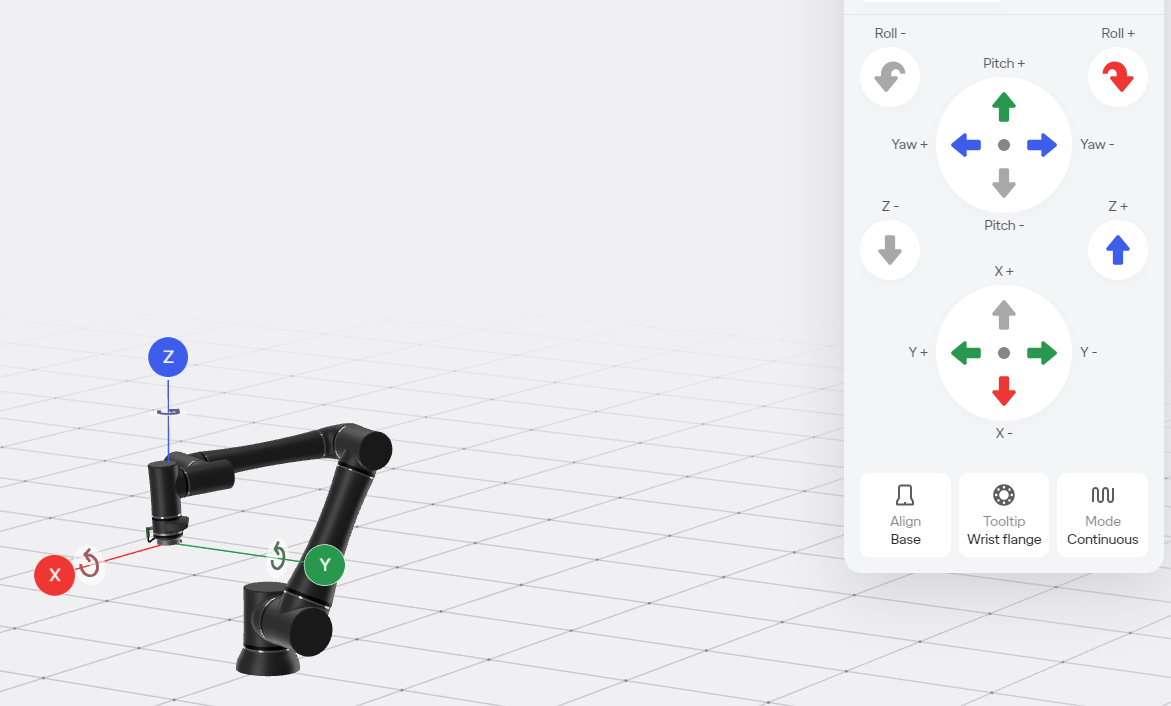
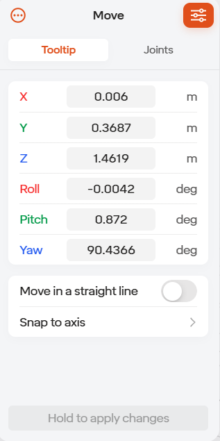
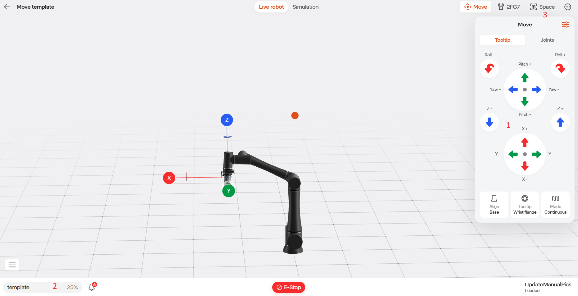
5.2.1 Jogging Tooltip
When jogging the tooltip, you are able to control the X, Y, Z coordinates of the tooltip, as well as the roll, pitch, and yaw.
This can be switched between “Base” (where the reference frame is the robot base), “Tooltip” (where the reference frame is on the robot’s tool flange) and “World” (where it is the same as the base unless you change the robot mounting angle for the base). Moving to tooltip mode can be useful for maneuvering the tooltip in and out of tight spaces.
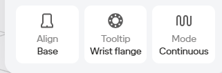
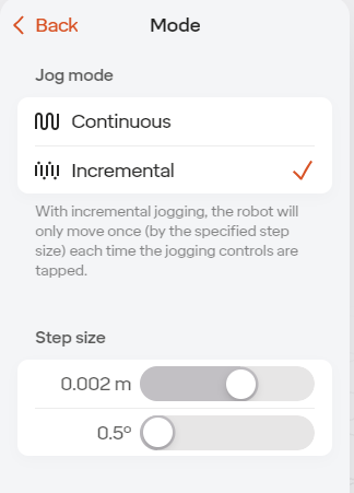
Selecting the “Mode” icon allows you to switch between continuous and incremental jogging. With continuous jogging, holding down a move robot icon will allow to robot to move as long as the icon is held down. With incremental jogging, when tapping on a move robot icon, the robot will only move a specified distance, this can be useful when fine tuning positions.
For safety, manually jogging the robot is always capped at a speed below the maximum that will apply when running. To make the robot jog even slower, you can change the global speed % slider in the robot menu.
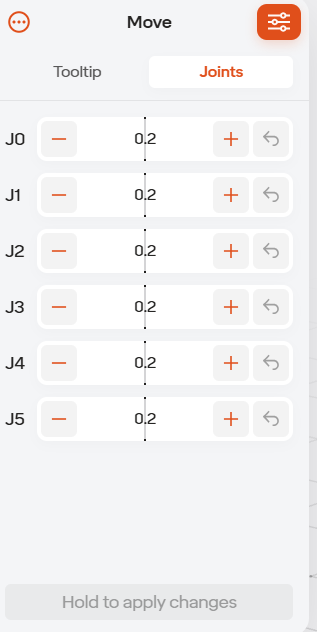
5.2.2 Jogging Joints
The robot’s joints can also be moved directly. This can be useful in avoiding collisions and in planning moves to minimize cycle time.
When moving the robot, there could be times when the robot cannot further move in a direction when the robot is not fully extended (certain actions will be grayed out). When this happens, check your Jog Joints tab to make sure there isn’t a joint that is at it’s joint limit.
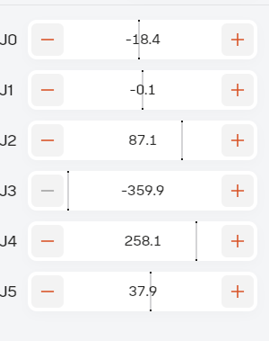
5.2.3 Entering Exact Values
When jogging in either mode, if you want to enter a more precise
value, you can press the  button in the top right. Once you’ve entered the
values you want, hold down the “Hold to Apply Changes” button at the
bottom of the panel.
button in the top right. Once you’ve entered the
values you want, hold down the “Hold to Apply Changes” button at the
bottom of the panel.
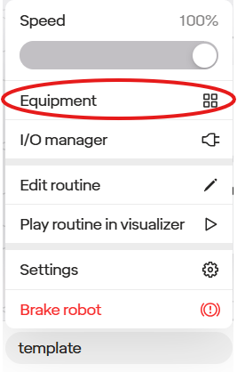
5.3 Managing Equipment
To manage equipment in the cell, including grippers, 7th axis devices, CNC machines, and more, open “Equipment” from the robot menu.
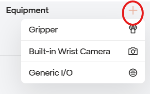
The equipment configured on the robot can be seen in the list on the left. To add new equipment, press the plus sign button in the upper right. Various settings for each connected device can be controlled on the right.
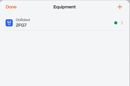
Currently, only one gripper can be added at a time (except when using the onRobot Dual Quick Changer). When adding a single tool on a single changer, you do not need to define a changer and instead simply add the tool.
To remove equipment select the equipment that you would like to remove.
Then select the ‘circle with the three dots’ icon at the upper right of the tab to reveal the delete icon.
Certain m8 equipment will need access to the flange inputs and outputs. To make your customer gripper for this equipment, to go to the Equipment tab, select the robot’s name in the lower left corner of the page and then select Equipment. Once here select the plus icon, then gripper, then custom gripper.
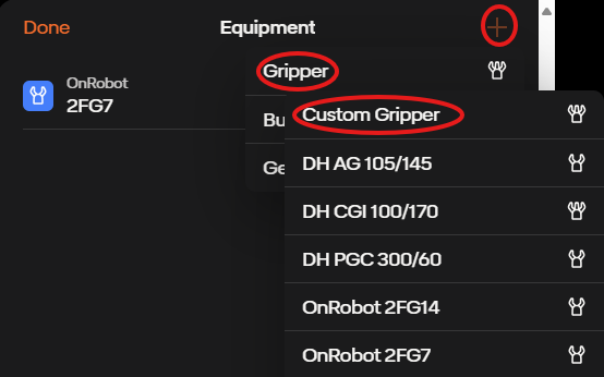
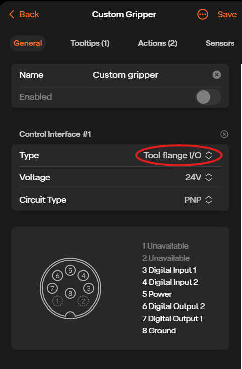
In the custom gripper page, select Add Interface, and then change the Type to Tool Flange I/O. Here you can view the pin map, change the voltage from 24V to 12V and change the circuit type from PNP to NPN
In the Tooltips tab you can add a new tooltip and adjust the TCP offset and rotation of the equipment. In the Actions tab you are able to control the actions such as actuate, reset, clamp, unclamp. You can also change the control from the control box I/O to the tool flange I/O. And in the sensors tab you can add sensors and change their input ports.
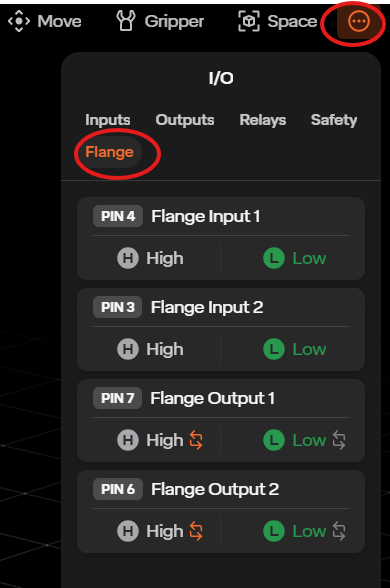
To access the flange I/O in the move robot page, go to the three dots icon in the upper right, select I/O, then select Flange.
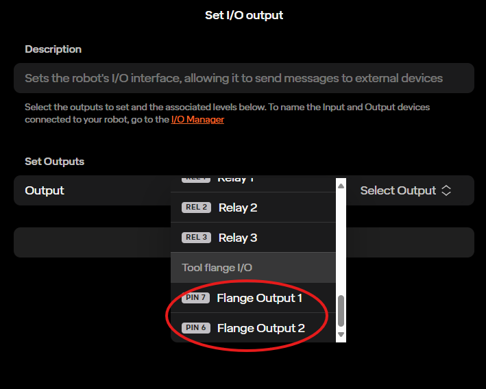
To access the flange outputs in the routine editor page, go to Add Step, then select the Set I/O Output step. On the right side of the page there will be a list of outputs to select. At the bottom of the list will be the flange outputs.
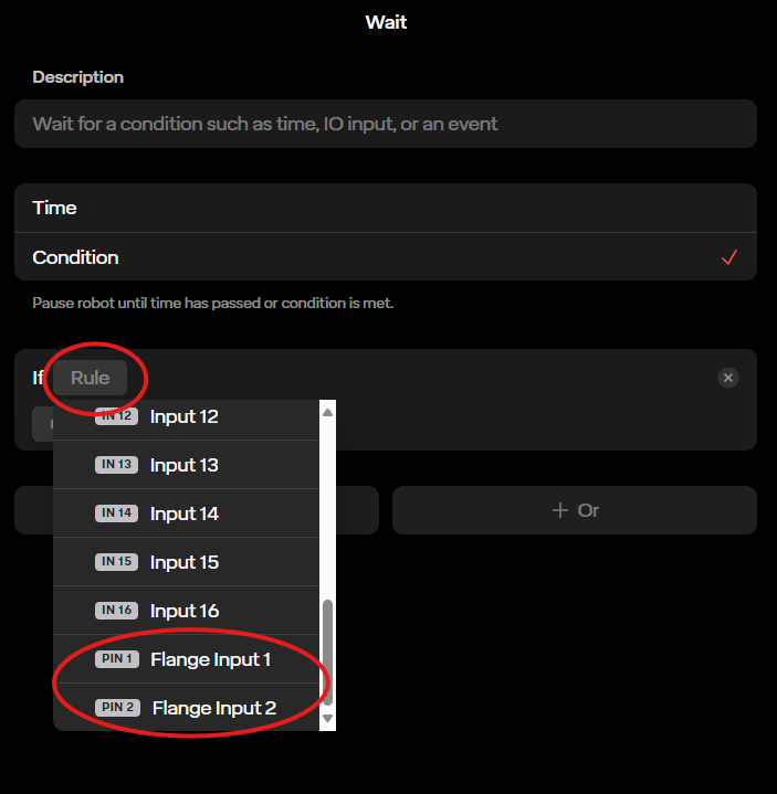
You are able to access the flange inputs for routines as well. For example, in a wait step, select Rule, then I/O, then at the bottom of the list you can find the flange I/O. So in this wait step, the routine will wait until one of the flange I/O goes high or low.
5.3.1 Custom Base/ Mounting Angles
As of recent software versions, you are now able to add your custom base/ custom mounting angles to your robot’s equipment page. If you do not see the option to create a custom base, please reach out to the Standard Bots support team.
Select the plus icon at the top right of the Equipment Page. There you will see an option called Custom Base/Mounting.
You will then be brought to the Custom Base creation tab. There you are able to change the mounting positions of the robot, as well as the rotation of the robot. You will also see some presets for the rotation. Those are upright (the standard), wall mount, ceiling mount, and custom.
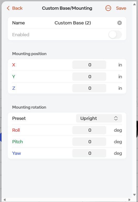
When done making changes, select the save icon in the upper right.
Once saved, you should see the robot model on your screen change to what you set your custom base/ mounting angles to be.
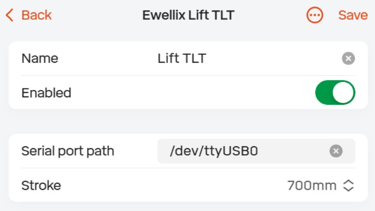
5.3.2 Vertical Lift
Step 1: Adding Lift Equipment In the UI, go to the bottom left hand corner and go into your equipment manager. Once there, select the “+” icon. Afterwards you can select the Ewellix Lift. Select the save icon and the lift will be added to your equipment list. Please reach out to support if you are unable to add the lift to your equipment list.
Step 2: How to use the Move Lift Step
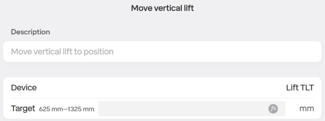
Go to your routine and add the “Move Vertical Lift” step.
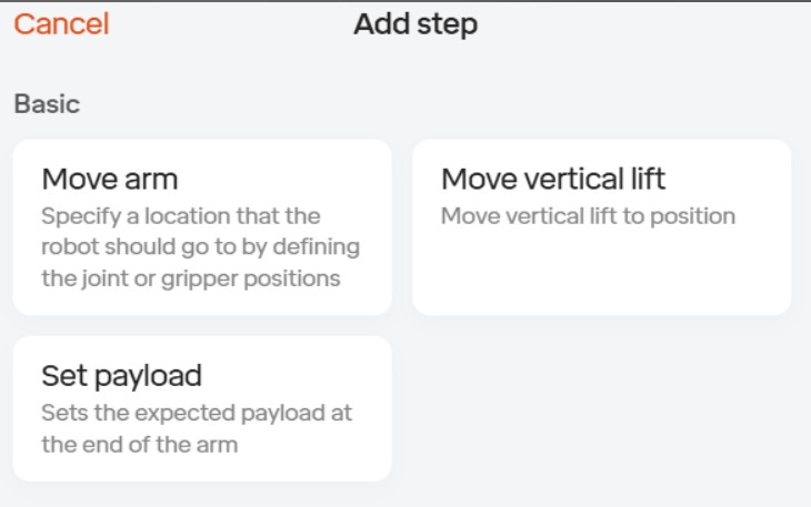
In the Lift step you can see the device selected as well as a target where you enter how high you would like the lift to move
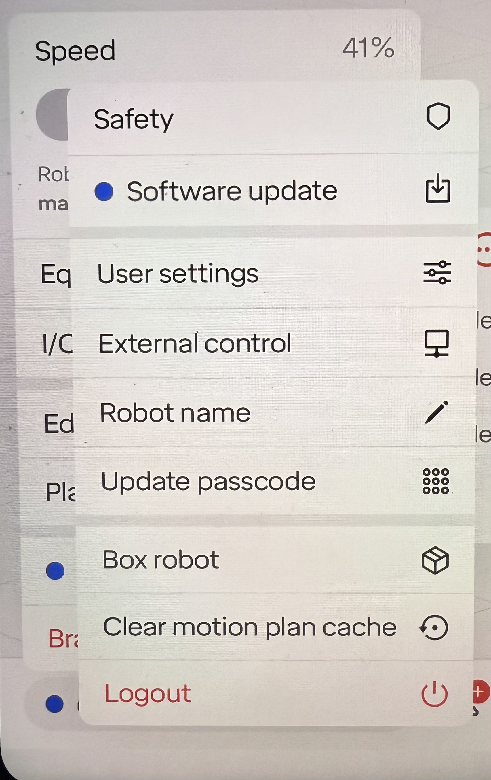
5.4 Robot Settings
Settings for the robot are accessed via the robot menu. User interface settings are accessed separately within settings via the hamburger menu.
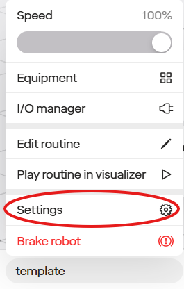
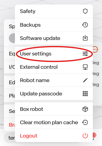
The following options are available on the RO1:
| Section Name | Description |
|---|---|
| Safety | Speed limits, configuration of safeguard devices connected to I/O ports, and collision sensitivity settings |
| PIN | Update the robot’s PIN |
| Robot Name | Name displayed in UI to distinguish it from any other RO1s you may be using. |
| Software Update | Allows checking for and installing any available software updates |
| Interface Settings | Allows switching between imperial and metric units for displaying lengths in the UI |
| Box Robot | Places robot into pose that allows it to fit in Standard Bots’ provided foam case in case it needs to be returned. |
5.5 Singularities
A singularity is a configuration in which the robot end-effector becomes blocked in certain directions. A robot is unable to maintain a constant velocity while passing one.
The RO1 handles this by never planning motion paths through singularities. If the robot is programmed in a manner in which it will encounter a singularity, the UI will display a “Motion Planning Failed” error and the robot will not attempt the movement.
To ensure routines are not created in which the robot will encounter a singularity, the user interface requires a play-through of any new routine in a simulation mode before running it on a real system. This ensures all motion plans are valid before running on a physical robot arm.
5.6 Routines
Standard Bots uses an intuitive “no-code” approach to programming the RO1 robot. The programs in the robots are referred to as “Routines”. The routine reads as a story. Routines can be developed and tested in simulation without moving the actual robot. The robot can store multiple routines. Routines contain all information the robot needs to complete the programmed task including moves, speeds, setting/reading IO, communicating with external equipment and more.
5.6.1 Routine Creation Example
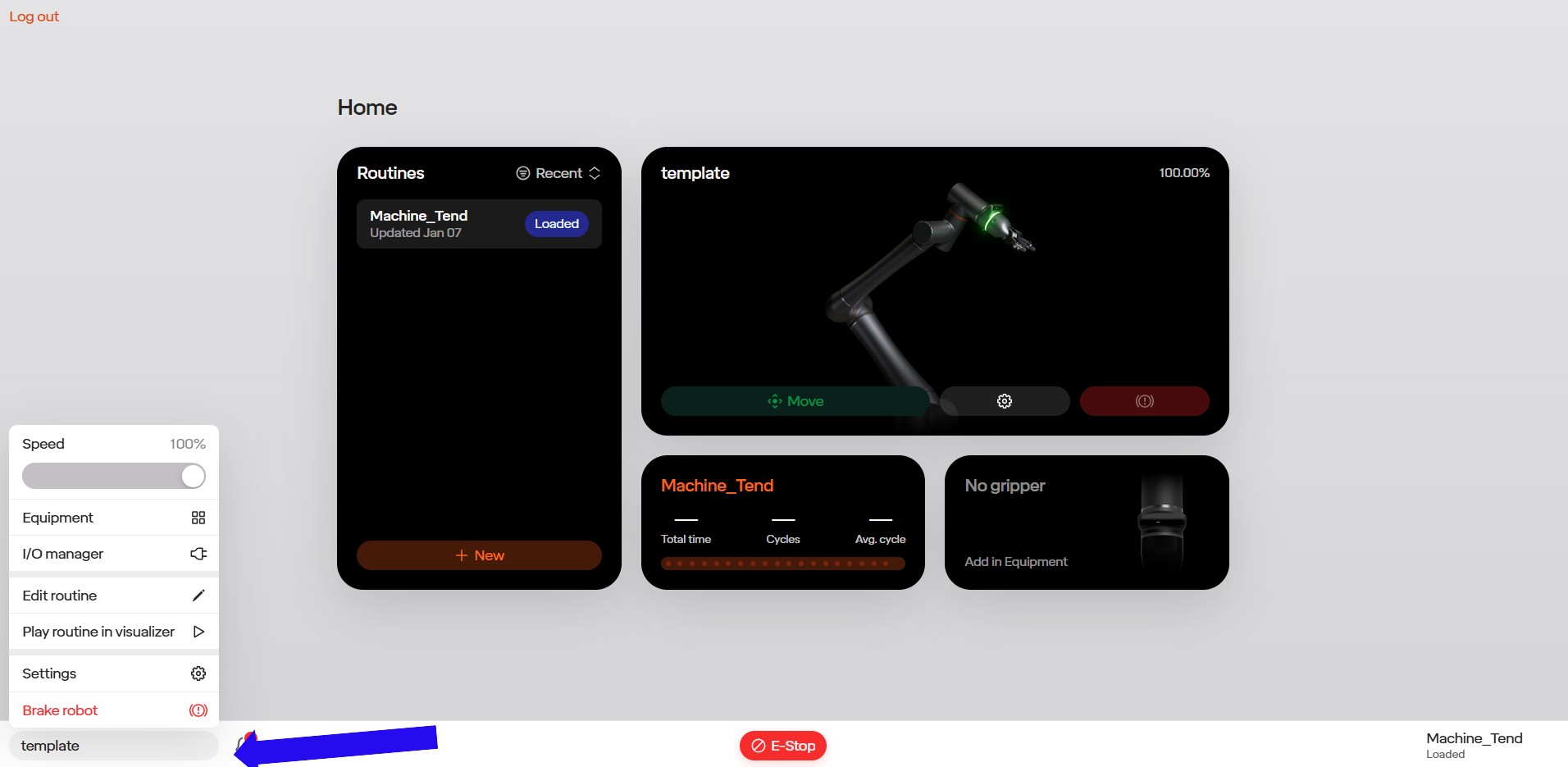
To get to the Routines area of the interface, return to the home page.
Existing Routines will be shown in the main window, and can be viewed and edited by clicking on them. To create a new routine select New.

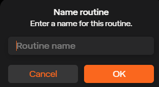
To create a new routine, give it a name under Routine Name.
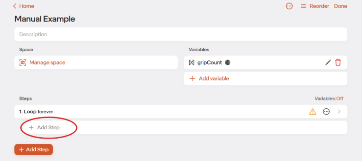
The routine interface is where you can add a description of your routine, and to edit and create steps.
1.Return to the Space.
2.Return to Routine list.
3.The Routine name.
4.Go to the Space.
5.Add variable to use in the Routine.
6.Lock or unlock editing.
7.Load this Routine onto the robot.
8.Add a new Step into the Routine.
9.List of Steps in the Routine
10.List of Step types that can be added to the routine.
If you are using a Standard Bots-supported tool, first add it using the manage equipment button on the robot page. If you are not using a supported tool, no need to add it. It will be controlled over I/O directly.
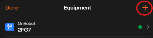
You will be directed back to the equipment tab to add the equipment. Click the +add to add the equipment. Select the equipment you have from the list. For our example, select OnRobot 2FG7. When adding a single tool on a single changer, you do not need to define a changer and instead simply add the tool.
Select the back arrow in the upper left to go to the Home Page and then select on your routine to return to the Routine Page.
Click Add Step to begin creating the routine.
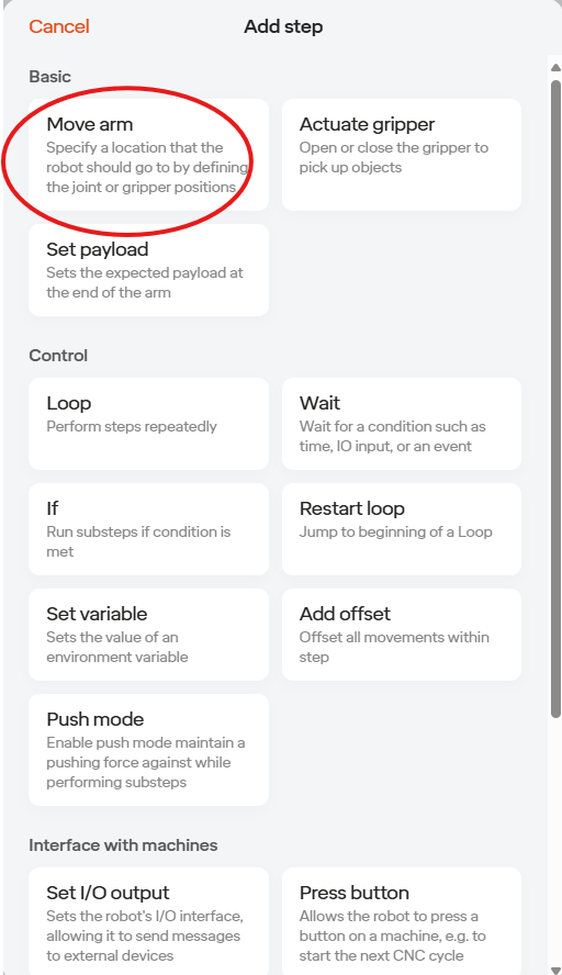
The menu will show all available step types with descriptions. For the sample routine, we will start with a Move Arm Step. A Move Arm step is how you tell the robot to go to a position. Click the Move Arm step to add it to the Routine.

The Move Arm step will be added to the first line of the Routine. The yellow ! Indicates that an action is required for that step. Click the step to edit the step.
Note: As of our most recent software release, the move arm step has been changed with the additions of waypoints and blending
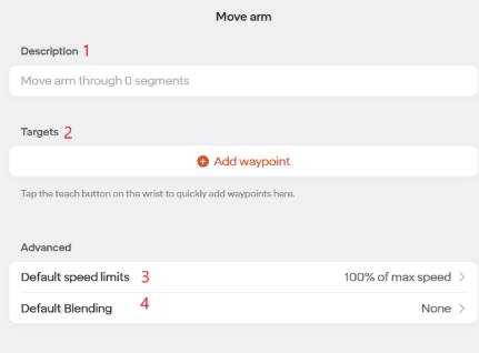
Editable description for this Step
Adding waypoints within this step
Changing the default speed limits for the waypoints within this step
Changing the default blending for the waypoint within this step
Below is the waypoint steps that are within the move arm step
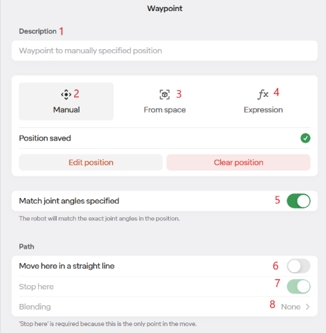
- Editable description for this step
- Specify the position for the robot to go to based on the current position.
- Specify the position for the robot to go to based on a saved position from the Space.
- Specify the position for the robot to go to based on a math function and/or variables.
- The robot can sometimes reach a point in multiple ways, this tells the robot to use this exact orientation when going to this point.
- Moving to this position in a straight line
- With multiple waypoints you get the option to stop at a position, or to pass through it. Note that the final waypoint step within a move arm step will always stop
- Edit blending for this specific step
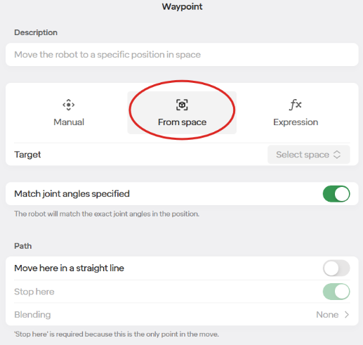
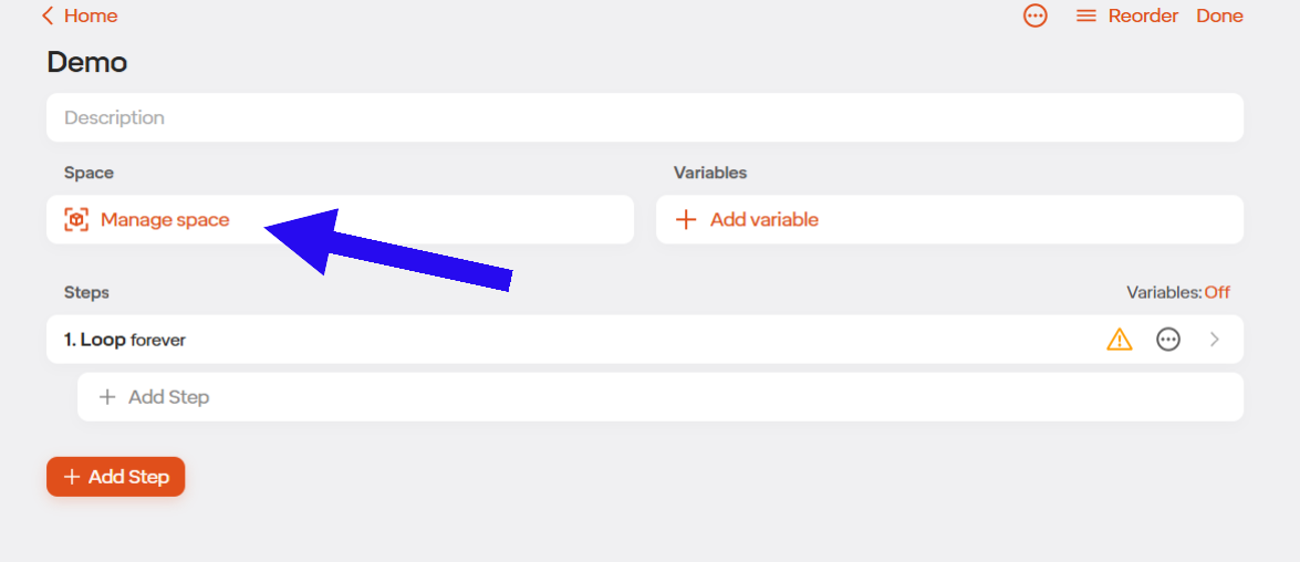
For our example we are going to select From Space. Defining a point in the Space allows you to use it in multiple places in the routine. Defining a point in the Space also lets you more easily modify the point in the future.
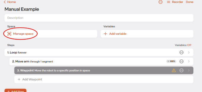
Select “Manage Space” to create Spaces
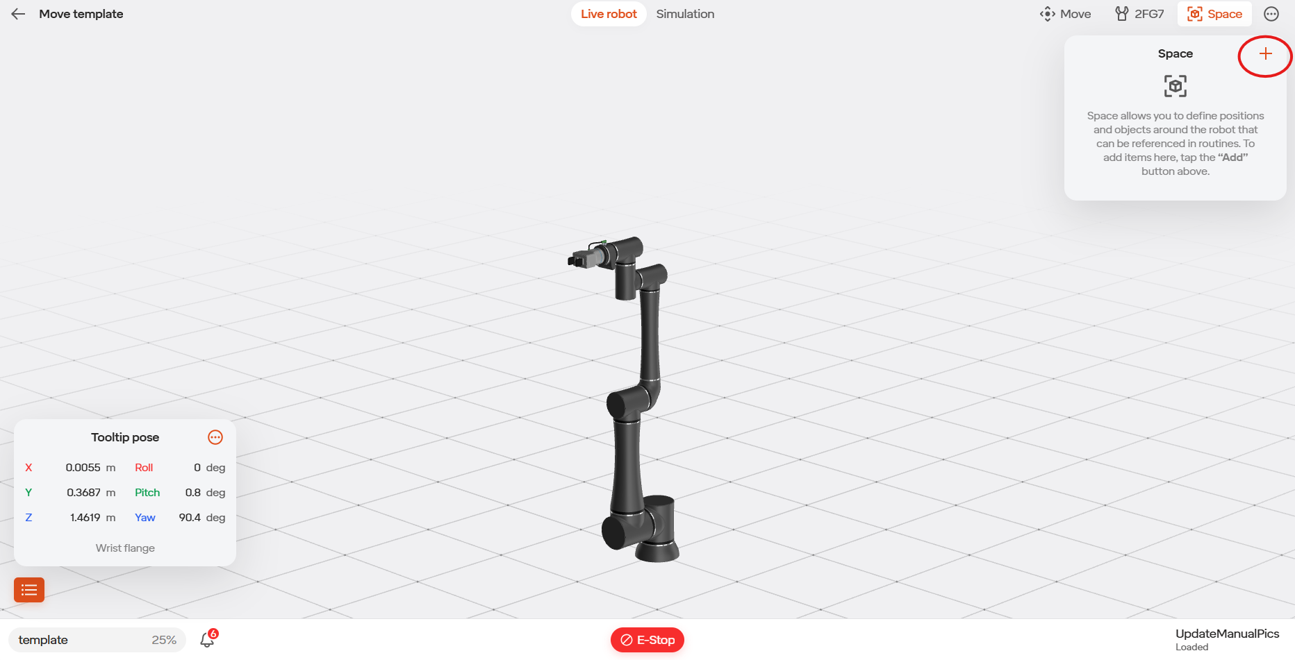
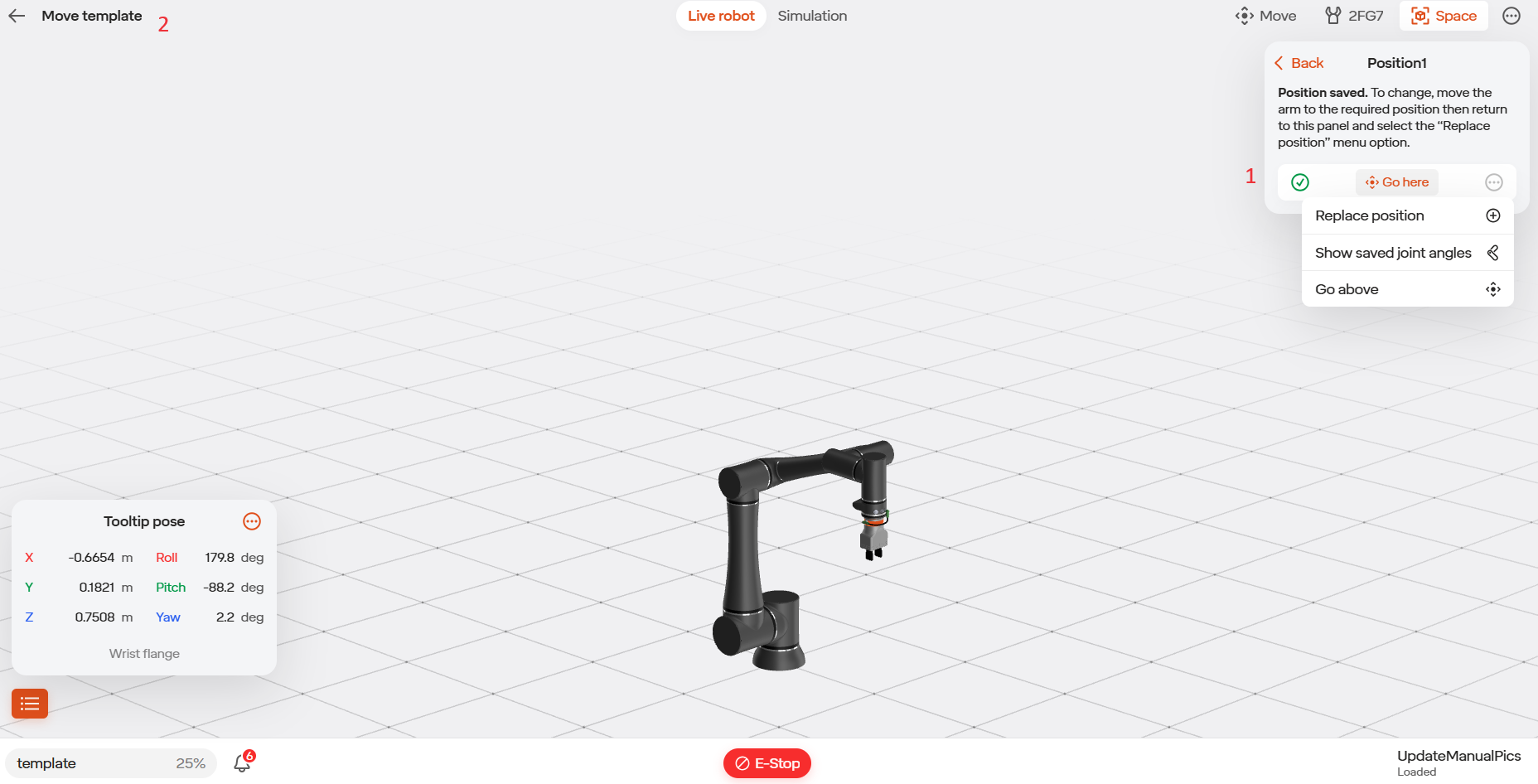
You will be brought back to the Move Robot view under the Space option in the upper right. Click the + button to add a new variable position.
Select Single Position to create a new saved position.
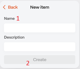
Give the position a name.
Select Create.
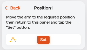
- Set will set the position named “Position 1” to the current robot location.
“Go Here” will drive the robot to the saved position if held down.
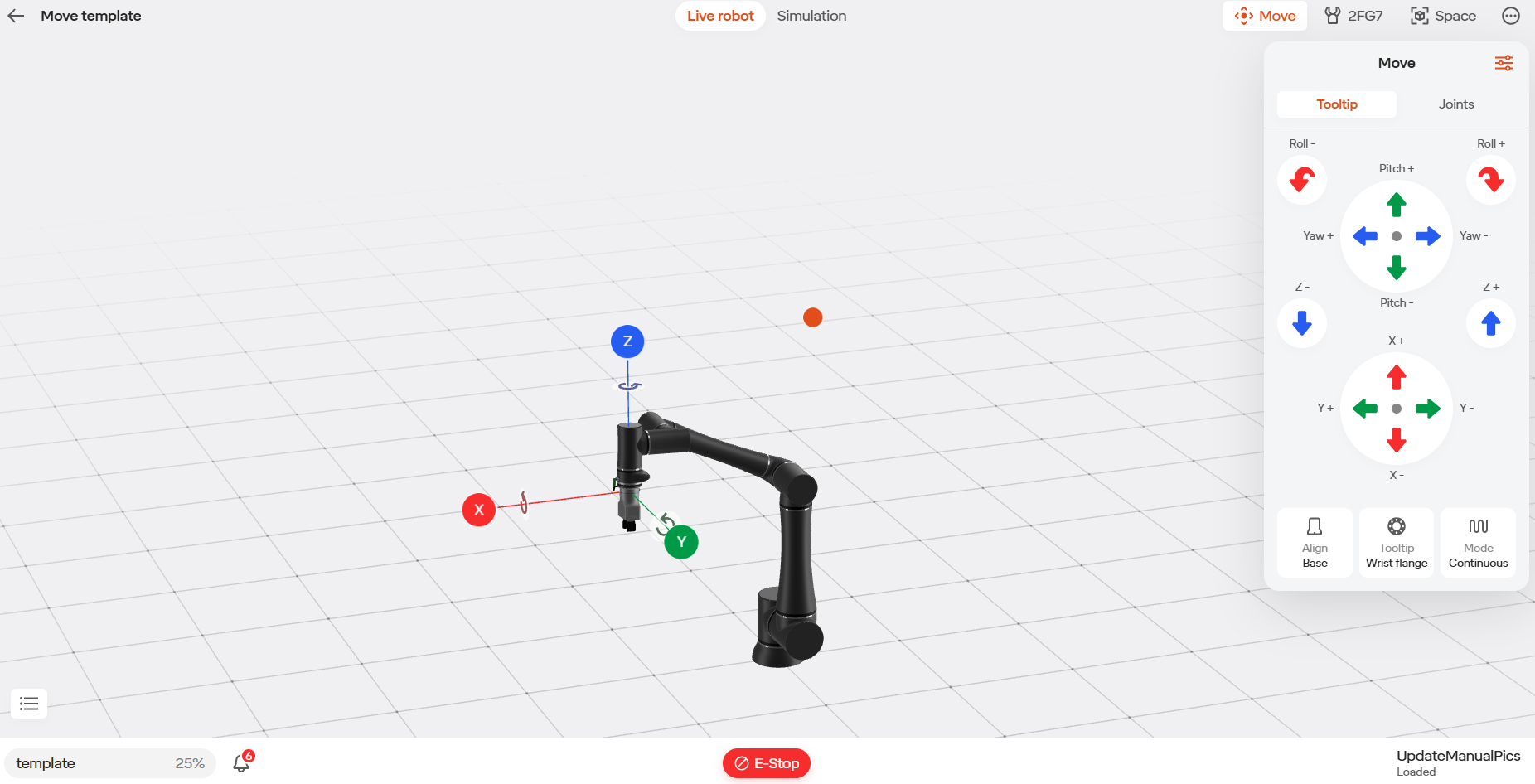
Use the Tooltip jogging area to move the robot to the desired initial position.
We are going to set a safe position above our work area for the robot to go to every time we start the routine.
Jog the robot to the desired position using the arrows.
If needed, use the menu to change the robot speed.
Once you are in the desired position, use the Space icon to return to the Space positions.
Set the position to the variable “Position 1”.
Select the back arrow to go back to the routine.
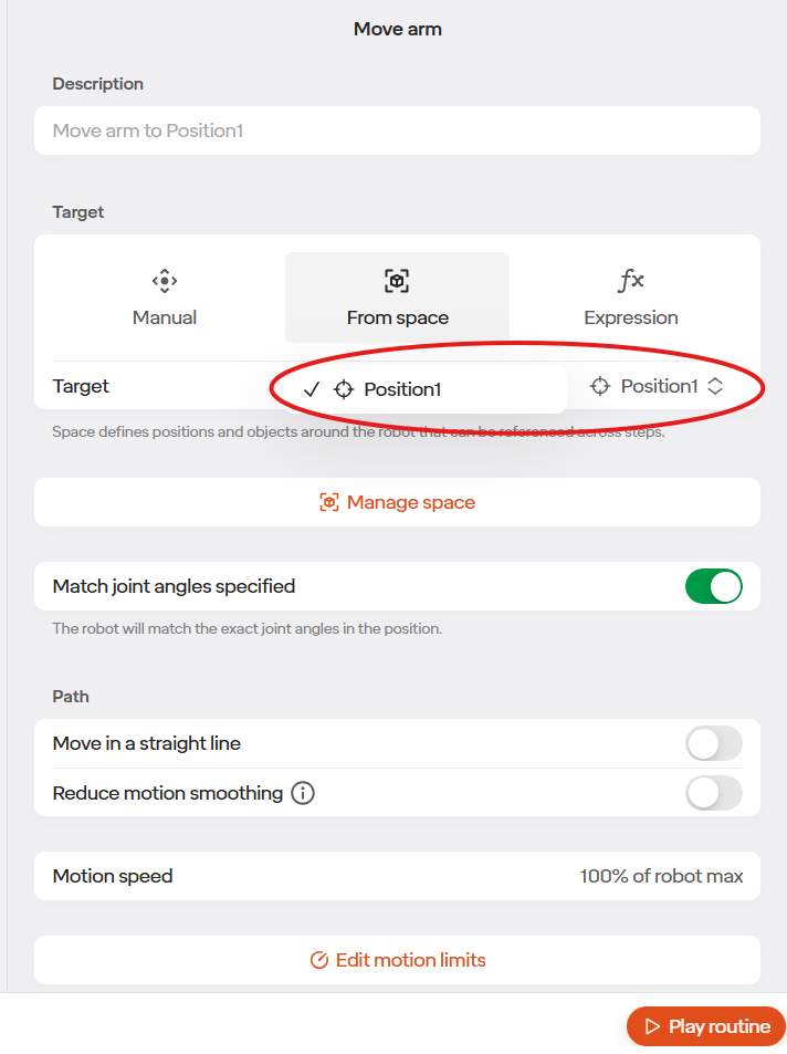
Select our new saved position “Position 1” from the drop down.
Create a step that is Below Position 1 and name it “Position 2”. Then add another waypoint step below the first waypoint step and add the new position
We have now completed our first Move arm step. Next add an Actuate Gripper step by selecting the three dots icon on the Move arm step and selecting “Add step Above”.
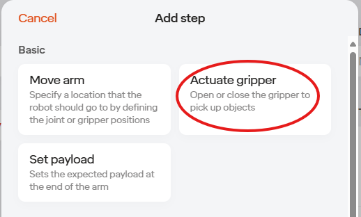
Often you will want to set your tool configuration at the beginning of the routine as you do not know how it will be left every time the robot stops. Select Actuate Gripper.
Select the Actuate Gripper the step to edit the step.
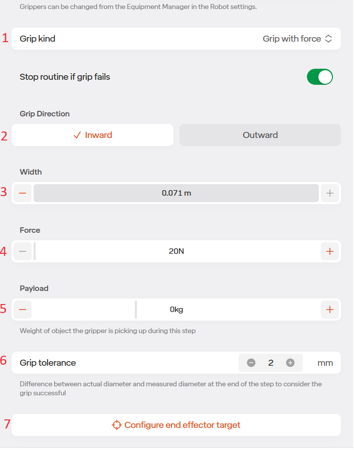
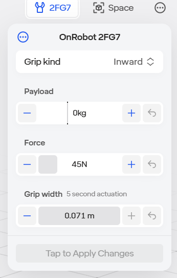
If we want to close the tool with some force select the Grip object with force checkbox. Since we are opening, we will change this option to Move To Position.
Set the GRIP DIRECTION to inward.
Set the gripper WIDTH, since we are opening, we will set it wide open
Set the FORCE to grip with. We will leave at 20N as we are opening.
Set the PAYLOAD for the target. Since we are just opening, this will be left at 0kg
Set the TOLERANCE for the gripper to be considered successful. This will be left at 2mm.
Click Configure End Effector Target.
The live robot page will open. Press the “Hold to Apply Changes” and then “Confirm End Effector Position” in the upper left. You’ll then be brought back to the Routine page.
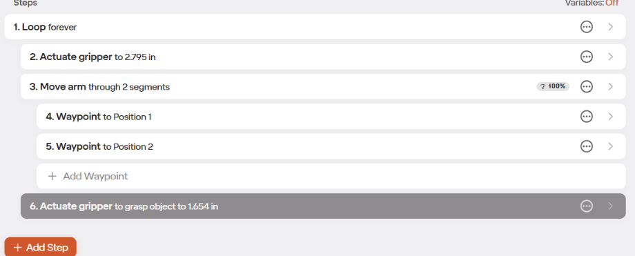
Next add a step below the move arm step that closes the gripper to simulate grabbing an object. The routine will look something like this.
Next we will create two more positions that will “place” the object we picked up. Name those positions “Position 3” and “Position 4”. Position 3 will be above Position 4.
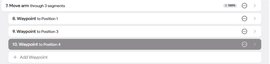
We will then add another move arm step that moves from position 2 (the previous position) to position 4. The move arm step should look similar to this:
Next add another gripper step, this time opening the gripper to “drop the part”. Once that is done add another move arm step that moves through the positions to position 2.
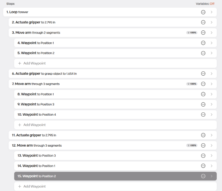
When done the final routine should look similar to this:
5.6.2 Running Routines
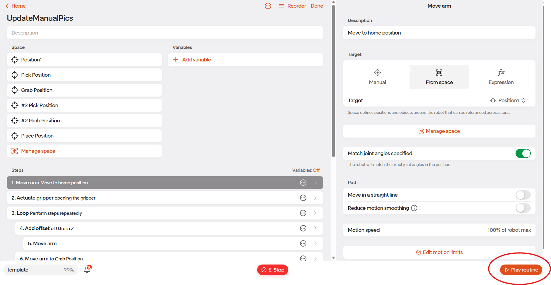
To test the routine, select the Play Routine icon.
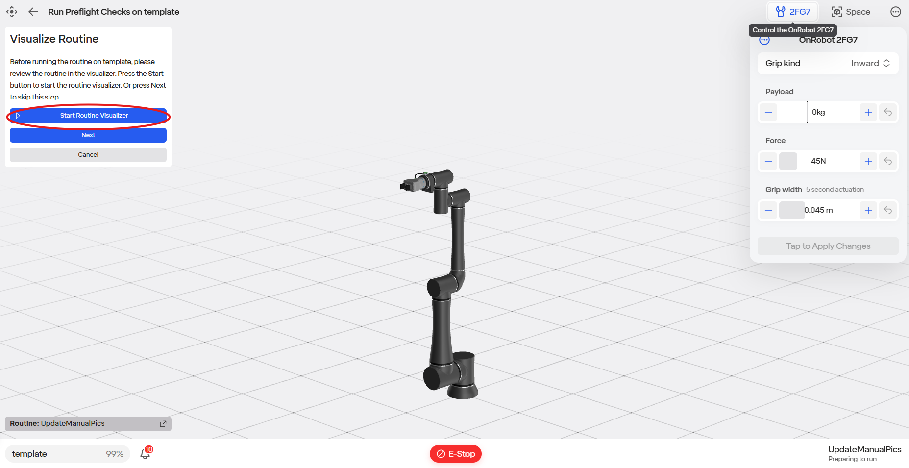
Select Start Routine Visualizer.
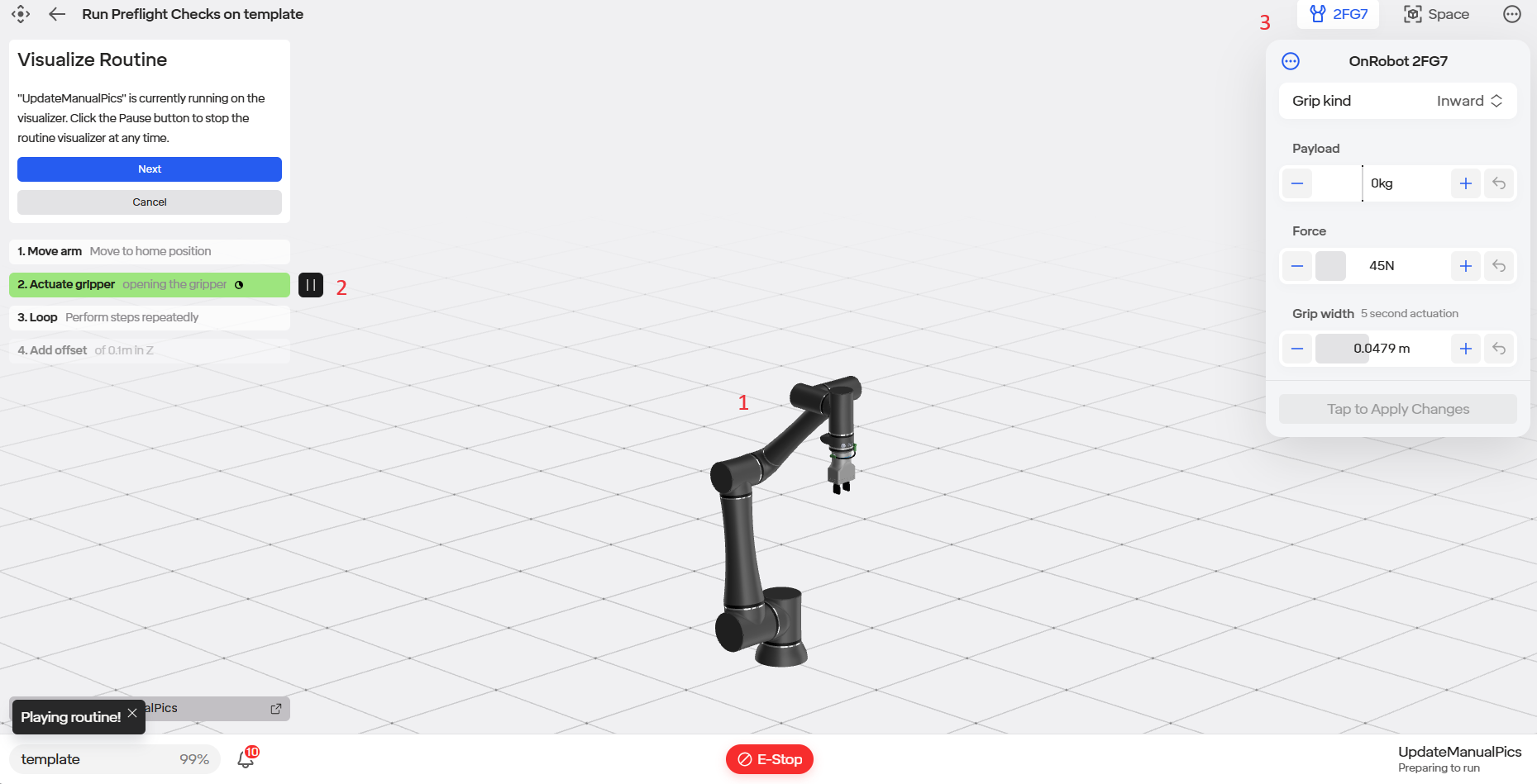
The robot will start completing the routine in a virtual environment.
The step the robot is currently completing will show on the left side of the screen.
The value of all Variables is shown in the upper right.
The routine will only loop once the first time. If you hit the “resume routine” button again it will loop indefinitely.
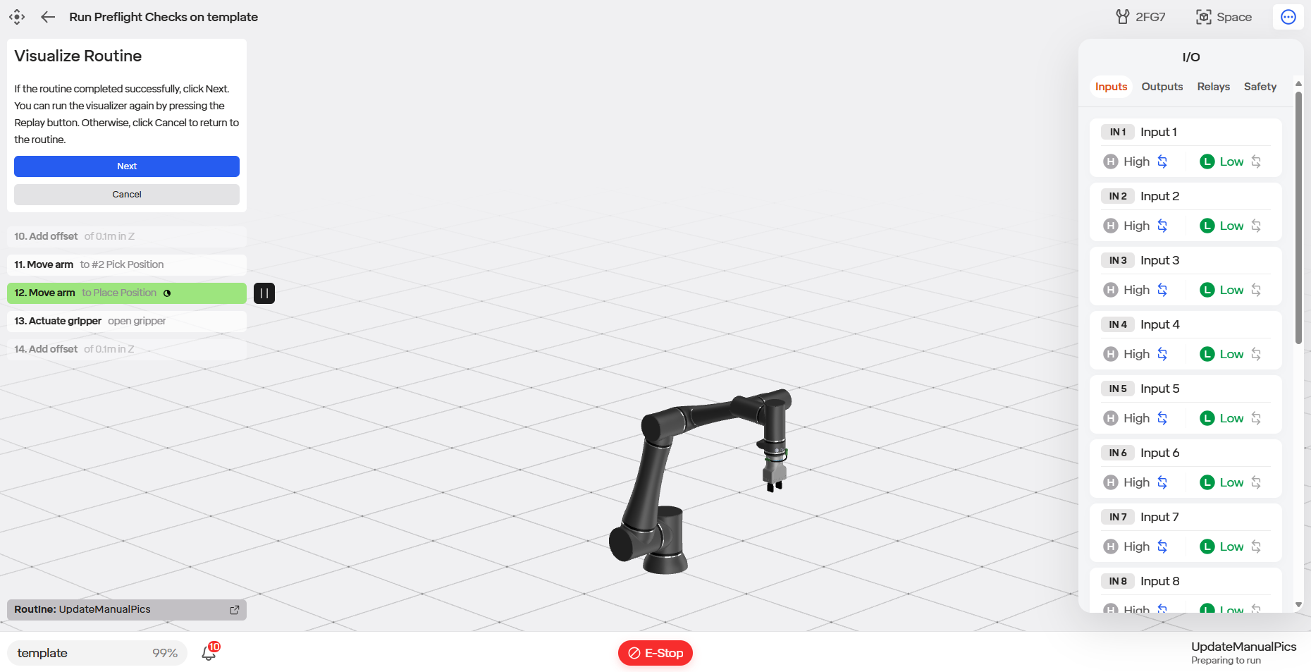
- The I/O menu (hidden behind the three dot icon in the upper right) can be selected to show the IO values as the routine is running.
1.The Gripper menu can be selected to show the tool settings as the routine is running.
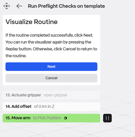
If the routine looks correct, it is ready to run on the physical robot. Select the blue Next button.
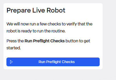
Select Run Pre-flight Checks.
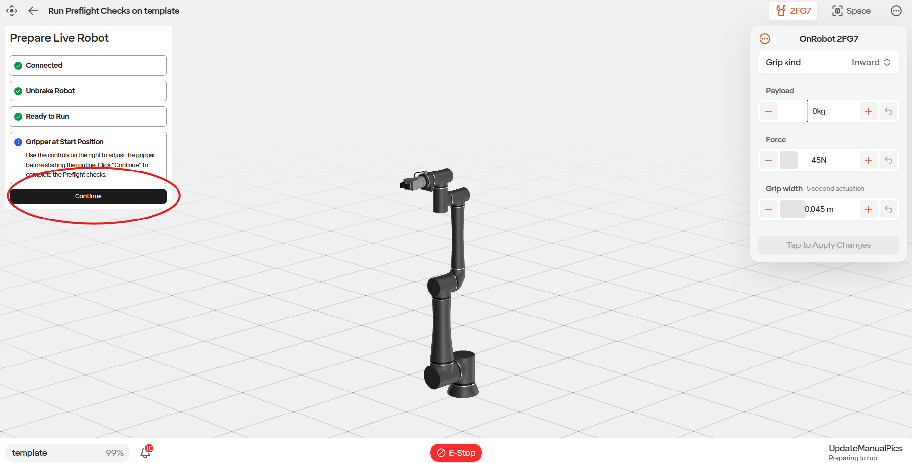
Ensure the tool is in an acceptable position based on the start of your program. In our case we start by opening, so ensure the gripper is empty if you don’t want to drop the product.
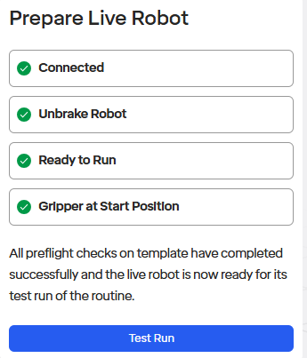
Click the blue Test Run button.
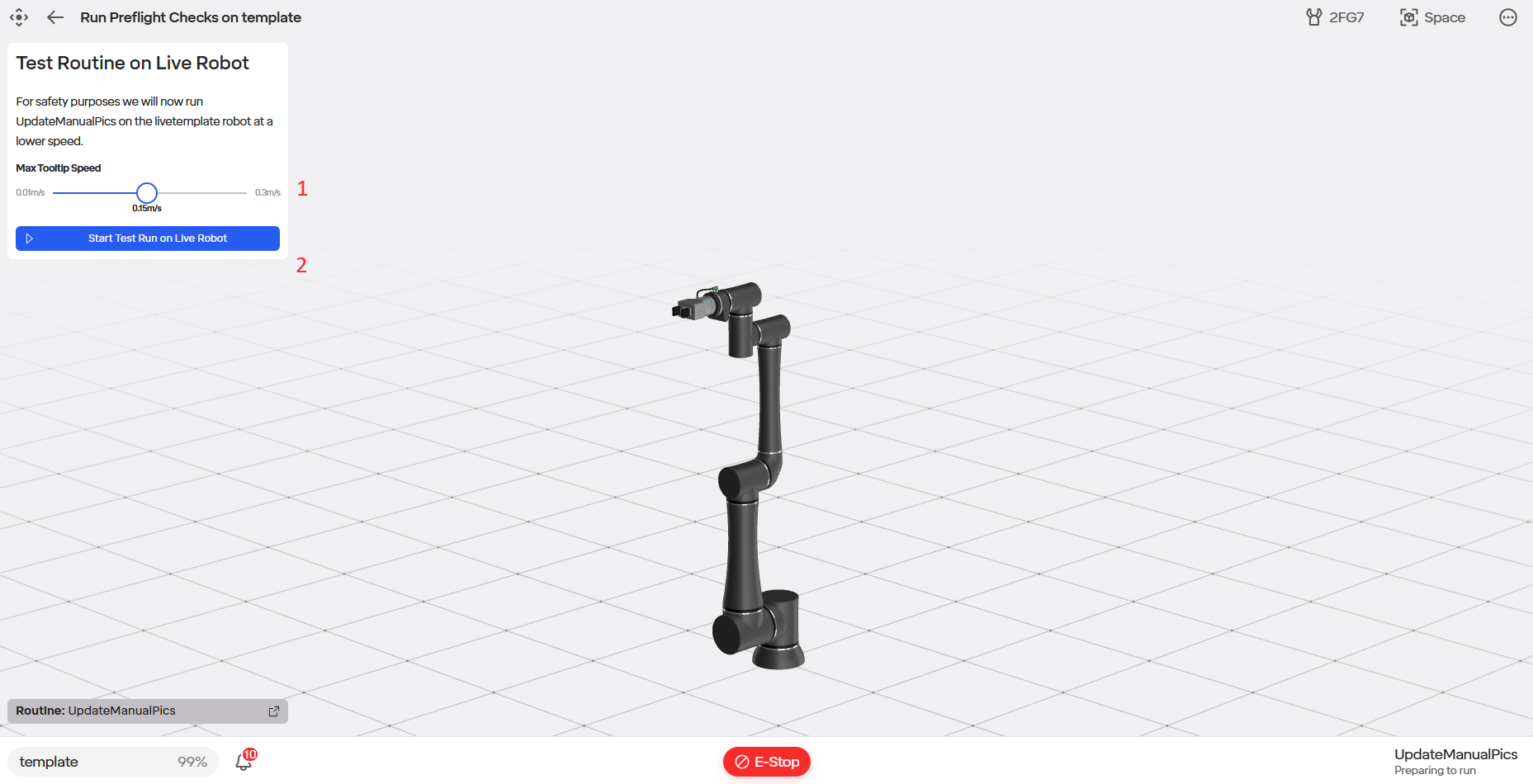
1.Select the maximum speed you want the end of the arm to move for the initial run by setting Max Tooltip Speed.
2.Click the Start Test Run on Live Robot button.
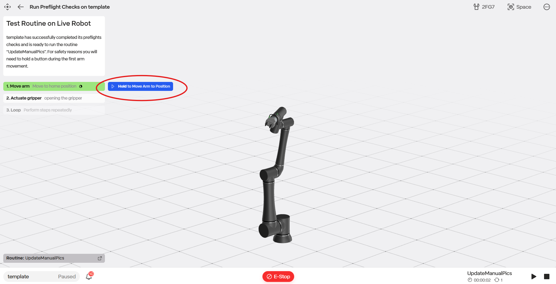
- Click and hold the Hold to Move Arm to Position button to move the robot to the first position in the routine.
- Watch the robot to ensure there are not going to be collisions during this move.
- The routine will run at the specified reduced speed once and stop.
- If the routine looks good, you can now play again with the “resume routine” icon that will appear in the upper right, and it will run at the speed specified in the menu in the lower left.
5.6.3 Accessing the Routine’s Schema
In the Standard Bots UI, you are able to access the routine’s schema. This allows you to copy, delete, and make changed to the schema of your desired robot routine.
To access the routine’s schema, first go to the routine editor page of your desired routine.
Next, select the three dots icon at that is located at the top of the page.
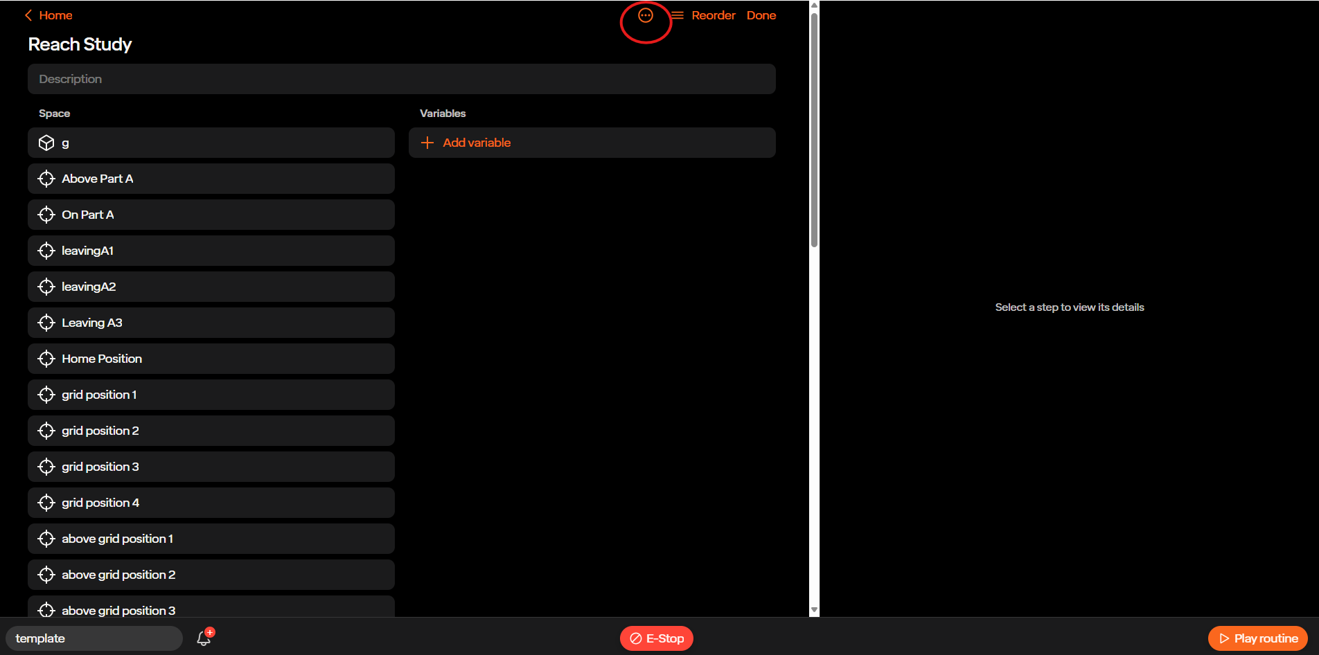
Then select the Schema icon
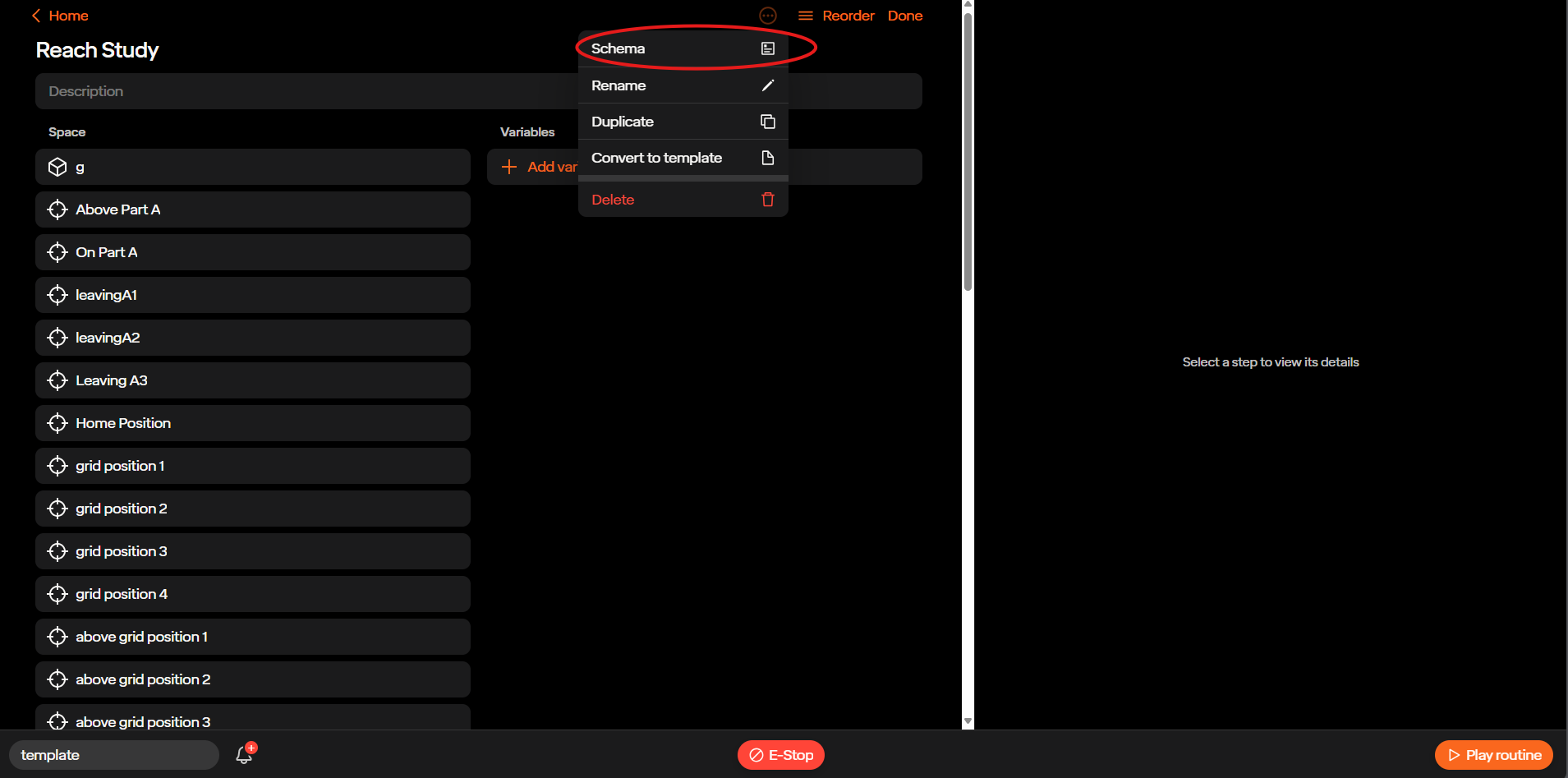
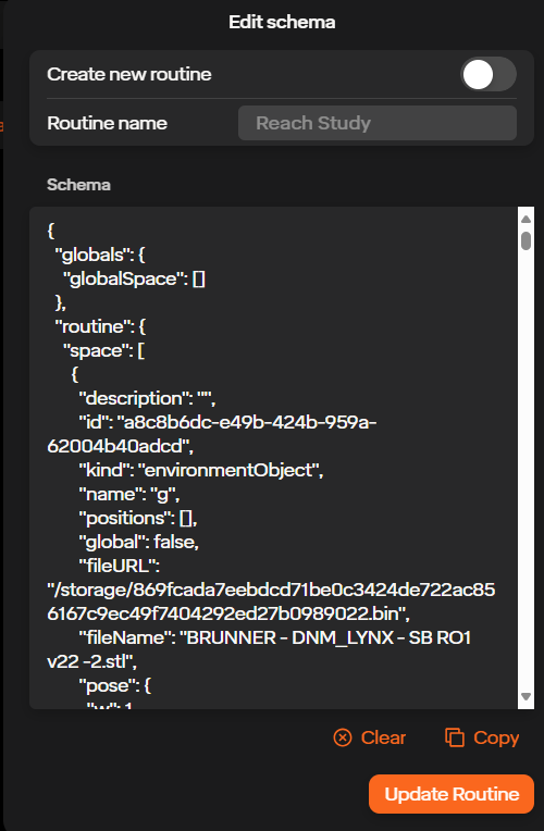
Once here you can access and make changes to the schema of your routine. At the bottom of the page are three buttons: Clear, Copy, and Update Routine. The Clear button deletes the schema, the Copy button copies the entire schema to your clipboard, and the Update Routine button saves the changes made to the schema. At the top of the page is a Create New Routine button. This allows you to create a separate routine with the changes you made instead of changing the existing routine.
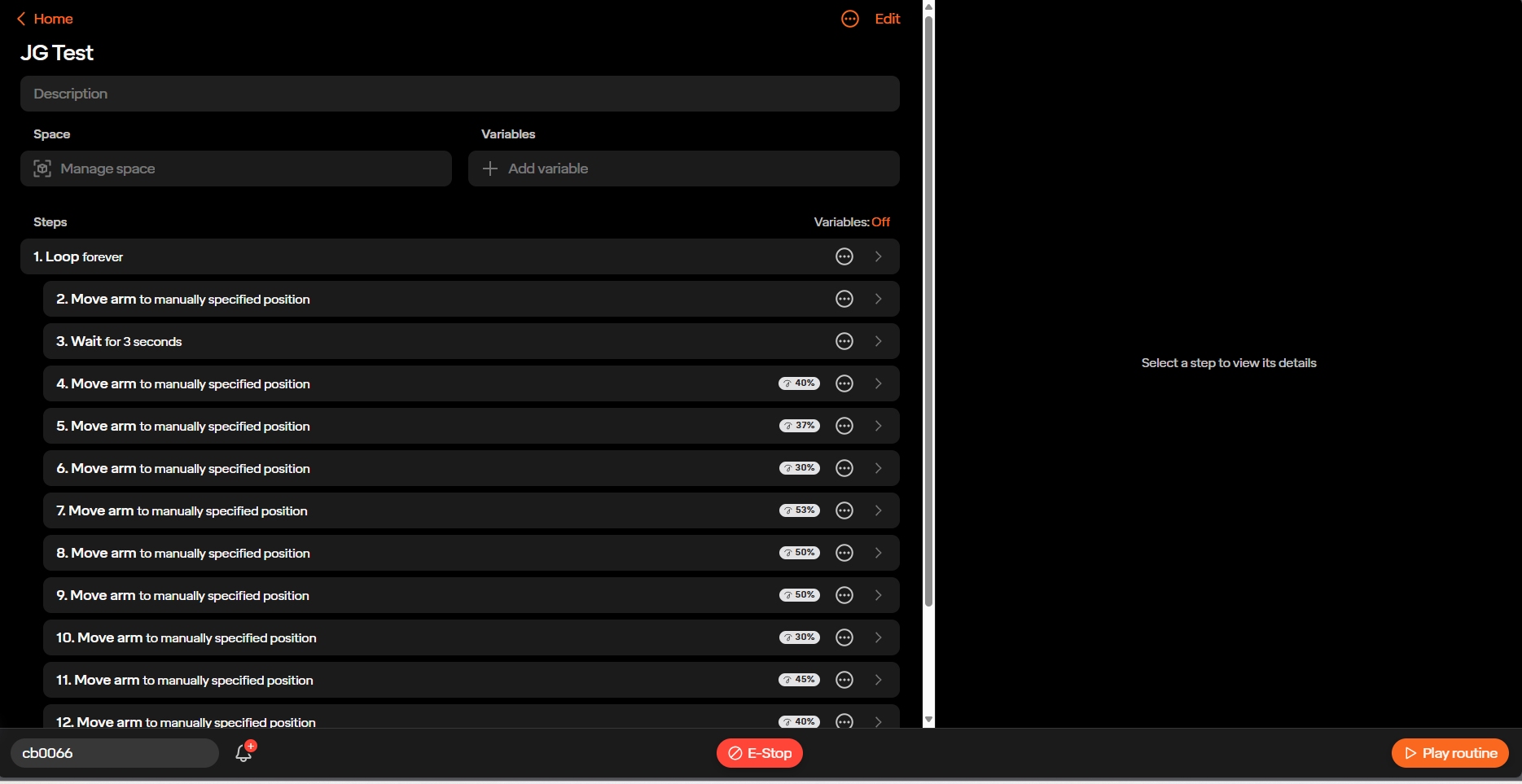
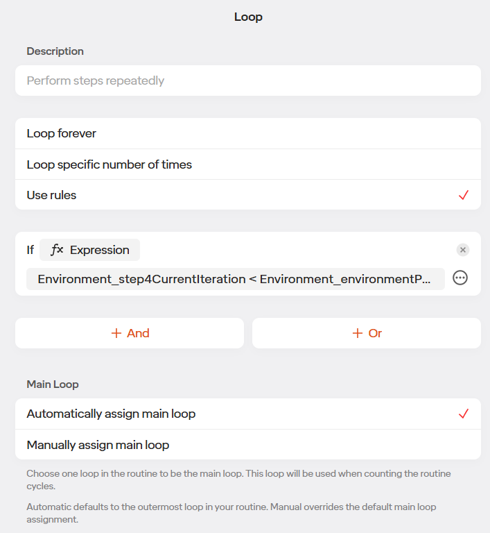
5.6.4 Loop Settings
With the preset loop settings, this routine will loop forever until stopped. If you would like to change the loop setting, select the first step.
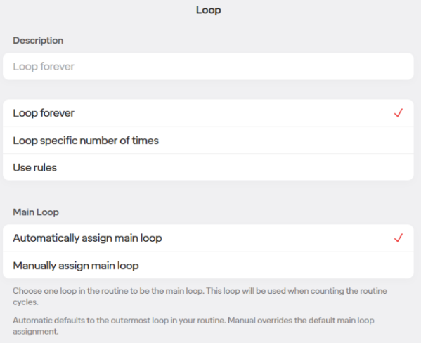
For Loop under Basic Options you can choose to:
•Loop Forever: Loop until the program is stopped by the user.
•Loop specific number of times: Loop the number of times specified before going to the next step.
•Use Rules: Allows you to use math and variables to set the number of times the loop runs.
For our case leave as Loop Forever
•Under Main Loop you can choose:
•Automatically assign Main Loop: Set the loop that is to count the number of times the routine runs as the one index most left in the routine window.
•Manually assign Main Loop: Set the loop that is to count the number of times the routine runs manually in the Loop setting using the checkbox below.
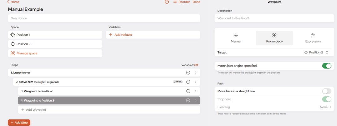
5.6.5 Waypoints
As shown above in the example routine, you are able to create waypoints by creating Spaces and then by selecting that Space as a target in a Move Arm step. There are three other ways you can move through a waypoint: Manual, Expression, and Relative.
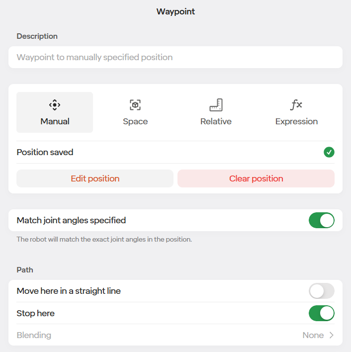
Manual is the easiest out of all the options. With that step selected you edit position and then move the robot to where you want that position to be and then save it. It is the quickest to create however it is the most limited, as you are not able to easily use this position throughout your routine as if you saved it as a Space.
With Expressions you are able to move to a position based off of an expression that you created. This can be accessed by selecting the Fx icon. To see more information on how to use expressions, go to section 5.7.1 to learn about Variables.
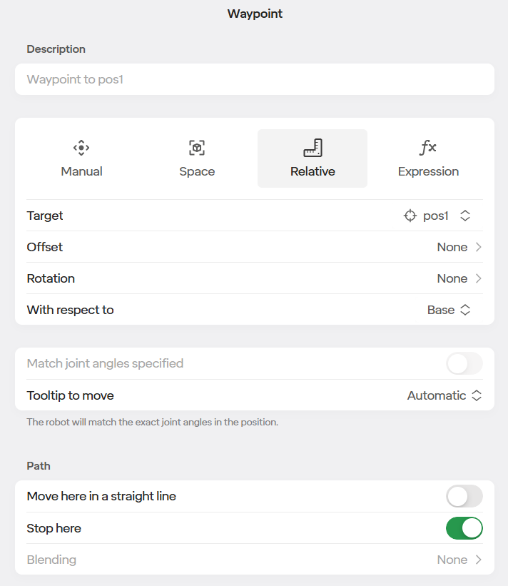
A relative waypoint step is similar to a waypoint step using a Space, however it has more features to allow you to make more complicated movements easier. Relative movements use Spaces as the tooltip position to move to but here you are able to change the Offset, Rotation, and with what respects the position is based on. With offsets you are able to use offsets in the XYZ plane based on the target position you select. Also with Rotation you are able to offset the pitch, roll and yaw from the position. These allow you to make multiple positions based off of one Space that you created. “With Respect To” allows you to base this position off of the base of the robot, the tool at the end of your robot, or of a plane that you created.
Relative waypoints are the most recent way added to move waypoints. If you do not see the Relative icon in your Waypoint step and if you would like to use it, please contact Standard Bots Support.
5.6.6 Stop Early If
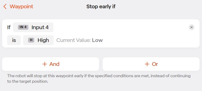
With newer software releases, the waypoint steps now have a “Stop Early If” feature. Please reach out to support if you do not have this feature and would like access to it.
With the feature, you are able to configure conditions that will cause the robot to stop at this waypoint, before reaching the target position.
This can be configured by having inputs, expressions, or expressions reach the desired conditions
5.7 Advanced Routine Functionality
5.7.1 Variables
Variables can be used to assist with a variety of tasks within a routine such as:
- Storing a part offset for use in multiple Add Offset steps.
- Keeping track of how many parts have been picked in a given
row.
- Keeping track of how many layers have been placed on a pallet.
To create a variable, locate the variables are in the routine editor.
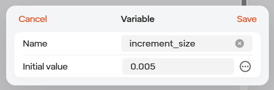
When creating a variable, be sure to set an initial value. If no value is set, the variable will be set to 0. The value in the initial value box will be used set for the variable every time the routine is started.
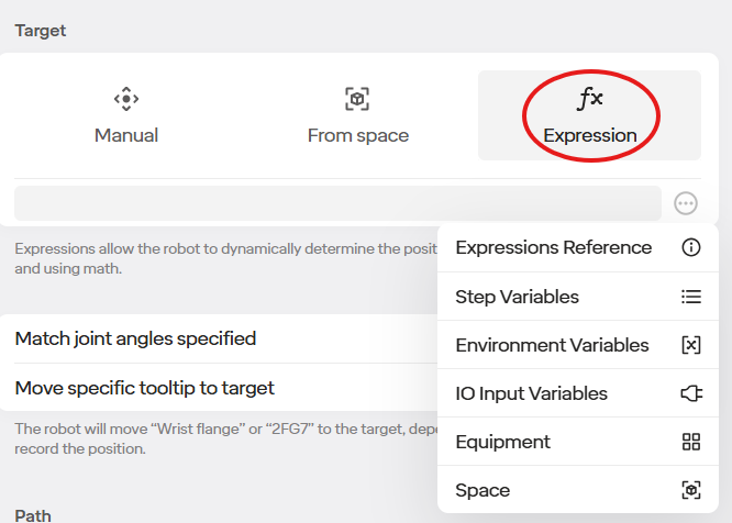
To use a variable in the routine, click the “Fx expressions” button in the given area of the step. There are several sets of variables available.
Expressions Reference: Help menu on how to construct expressions
Step Variables: Data from each routine step that can be used, for example the number of times it has been executed in a loop.
Environmental Variables: Variables created by the user in the routine.
IO Input Variables: Access to each of the 16 24VDC inputs, 0 if off 1 if on.
Gripper State: For supported grippers, inputs based on current state, for example closed or open.
Space: Data set in the space, such as saved positions.
Note: If you are using a variable, you must add it using the “Fx expressions” button and then go to the three dots icon to find what variable you want to use (custom variables made will be found in “Environment Variables”). Do not manually type it in. Manually typing the variable will not include the correct prefix and will result in an error.
Here is an example of how to “add 1” to the value of a variable:
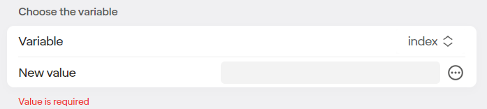
select the “set variable” step
select the variable you wish to add to (this example uses a variable named “index”)
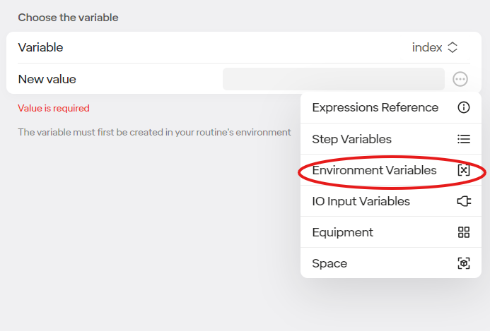
select the three dots icon and click “environmental variables”.
Then select the variable you wish to change, it should automatically appear in the value bar. Notice how it’s shown as “Environment_…”, typing in the name of your variable into the bar will not work.
Then put “+1” in the value bar.
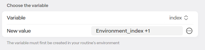
Now every time the routine gets to this step, the value of “index” will increase by one.
This doesn’t have to be only for addition, other math functions can be done as well.
5.7.2 Javascript
The Standard Bots routine editor provides the necessary instructions that address the requirements for the majority of applications. Should you need to to incorporate more advanced functions, the routine editor allows you to write your own JavaScript into Loops, Add Offsets, Move Arm steps, and more.
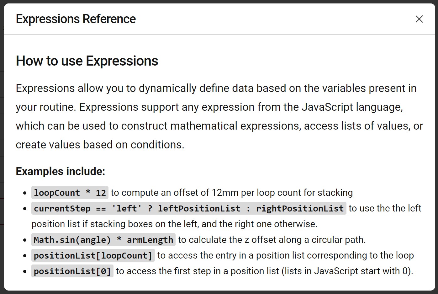
You can access the above help menu by clicking “Fx” in any text window in the routine editor and selecting “Expressions Reference”.
In the above example, this loop will iterate until the loop has iterated more than the value set in an environmental variable, partsPerRow. After the loop has iterated more times than the value of partsPerRow, the routine will move to the next step after what is contained in this loop.
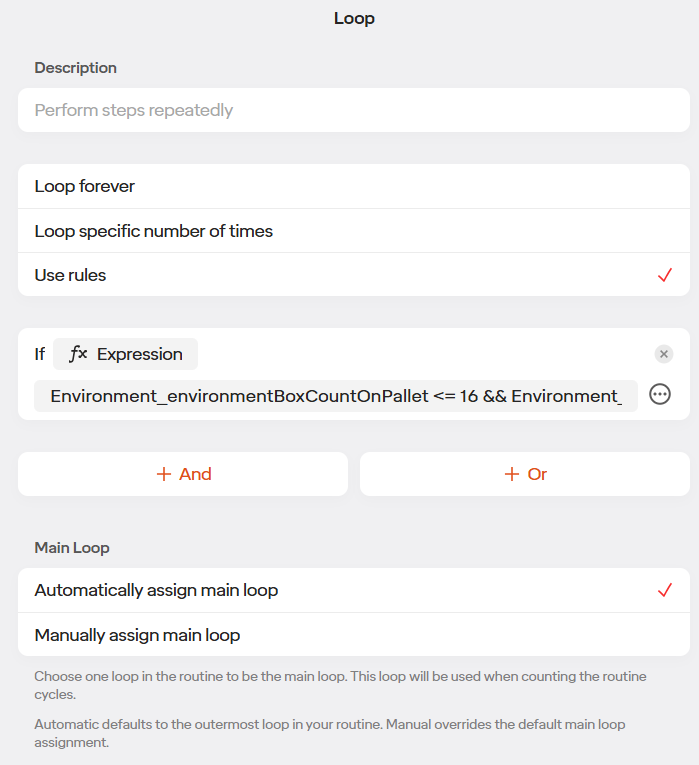
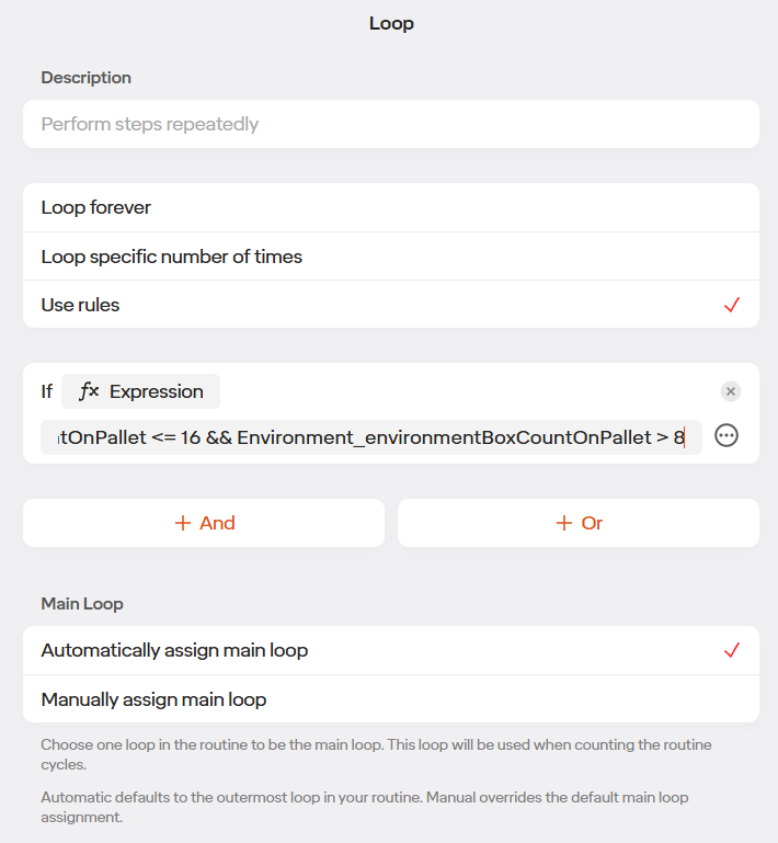
In the above example, the code is checking if a variable boxCountOnPallet is less than or equal to 16 but more than 8. If the above condition is true, whatever is indented below the If statement in the routine will execute.
Some Examples of JavaScript Code are Below:
| Command | Description |
|---|---|
| > | Greater Than |
| < | Less Than |
| >= | Greater Than or Equal To |
| <= | Less Than or Equal To |
| == | Equal To |
| === | Strictly Equal To |
| != | Not Equal To |
| !== | Strictly Not Equal To |
Basic Math Symbols Apply “+” for Addition, “-” for Subtraction, “*” for Multiplication, and “/” for Division.
Programming Example: We want to wait for Variable 1 to equal 18. That would be created in a If Fx Expression as follows: Environment_variable1 == 18 where Enviroment_variable1 is Variable 1 and we are waiting for it to be equal to 18 to continue the program.
5.7.3 Grid Position Lists
Grids are often used in robot programming when a large number of parts needs to be processed by a robot. Using the Grid Position List functionality when creating a routine can save significant time and effort.
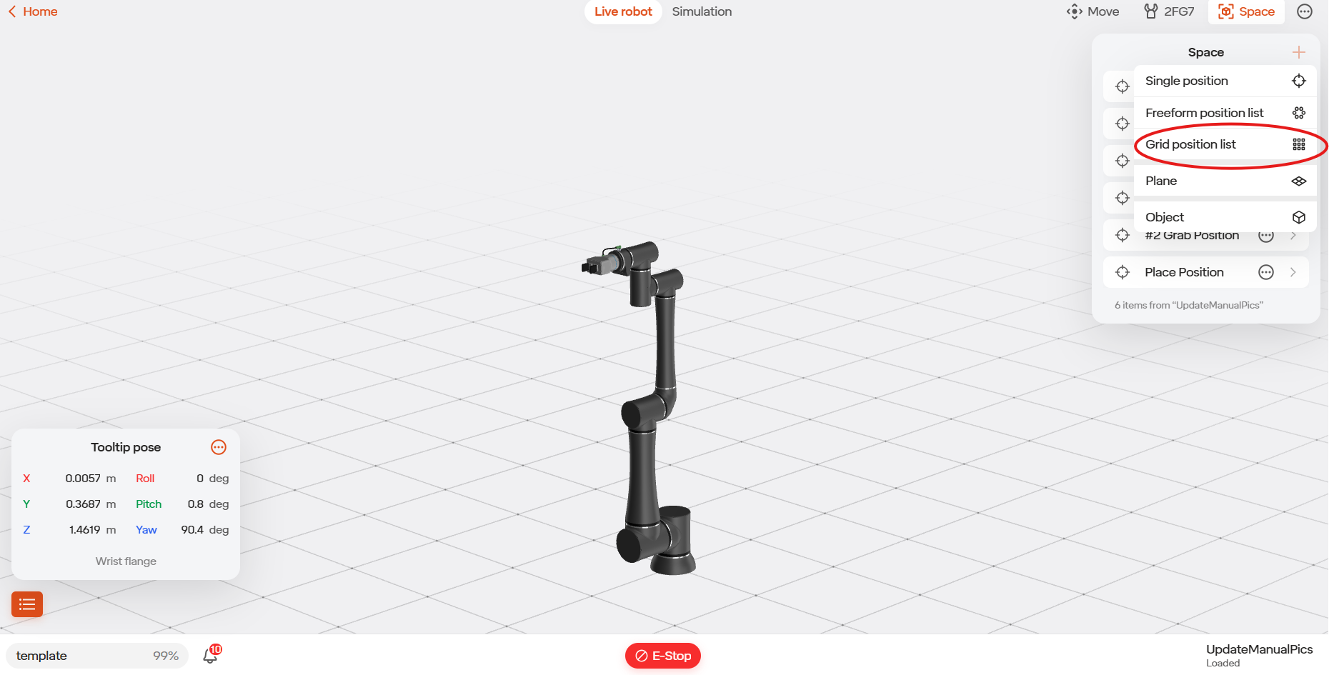
To create a grid, go to the Move Robot area, go to the Space (square icon), select the Plus icon, and then select Grid Position List.
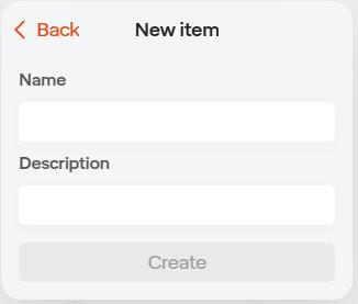
Give a name to the Grid Position List.
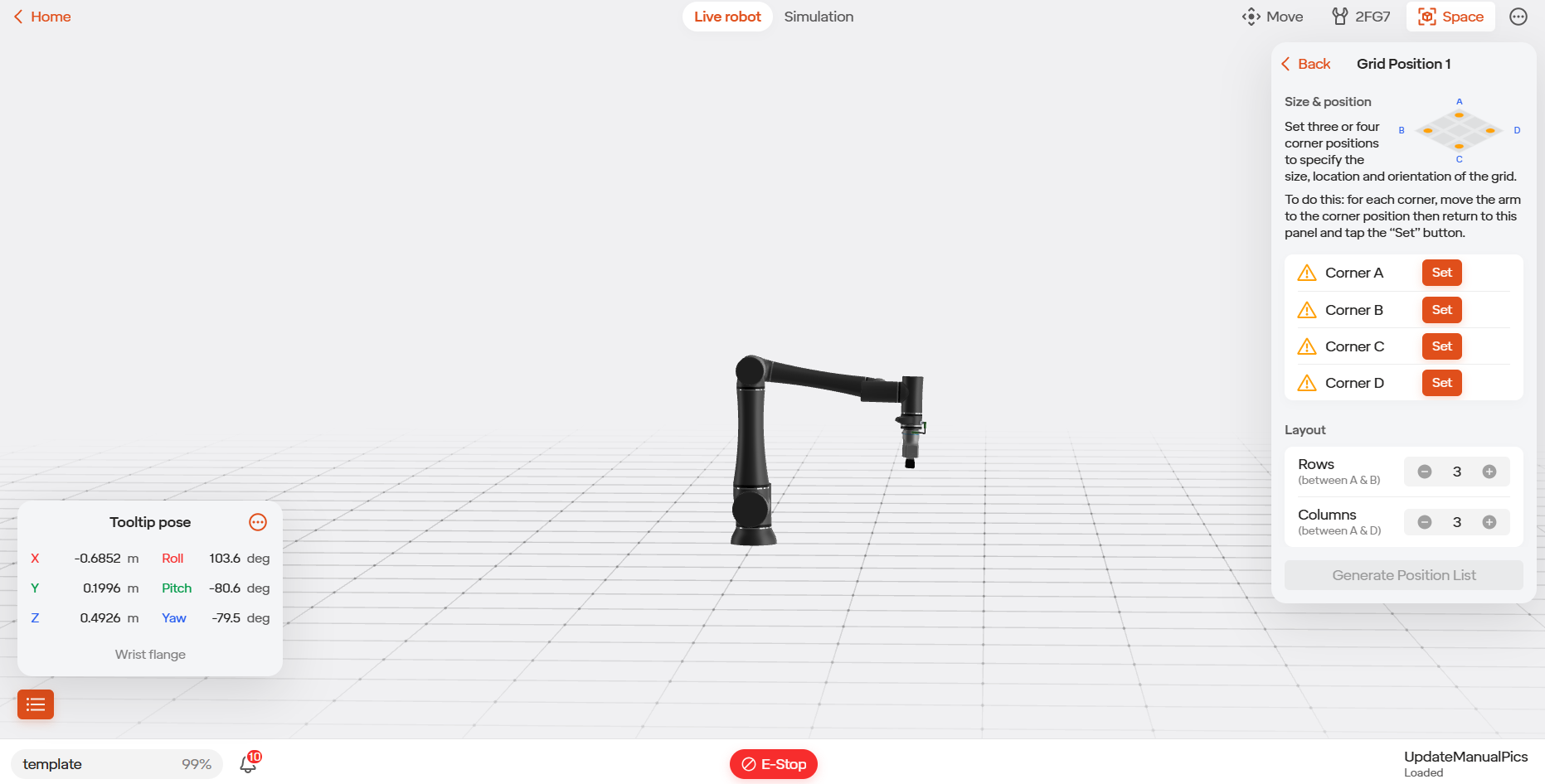
To create the grid, first drive the robot to a corner of the grid using the Jog Robot functionality in the Move Robot view. Set the position. Repeat for 3 corners of the grid.
Under Layout, select the number of rows and columns in the grid. This will be the layout of the parts within the grid.
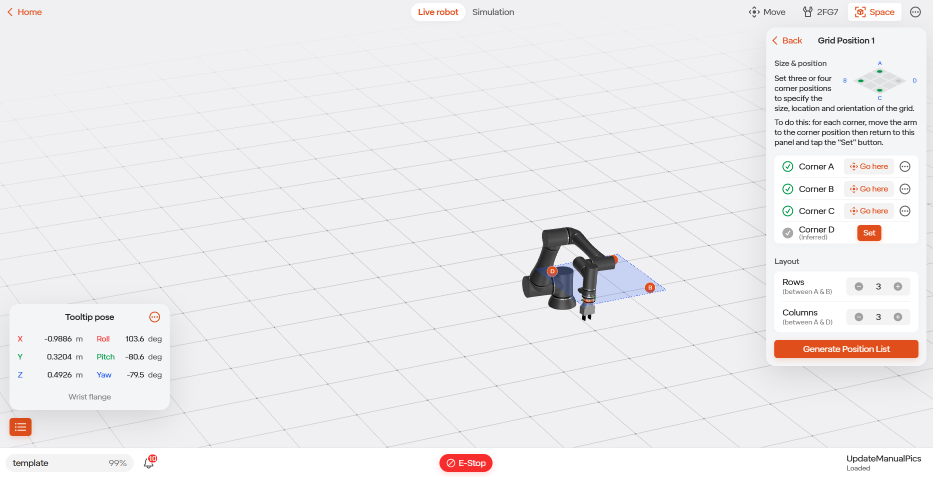
Select “Generate Position List”.
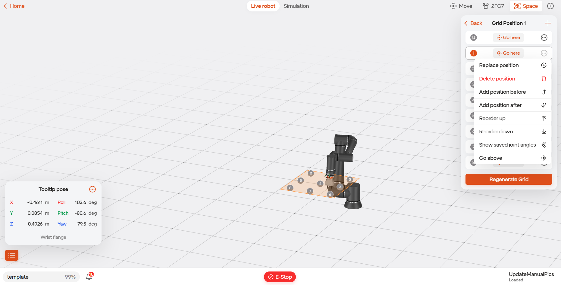
After the grid is generated, you can go to the positions using “Go Here”, tune them by using “Replace Position” (hidden behind the three dot icon), or exit.
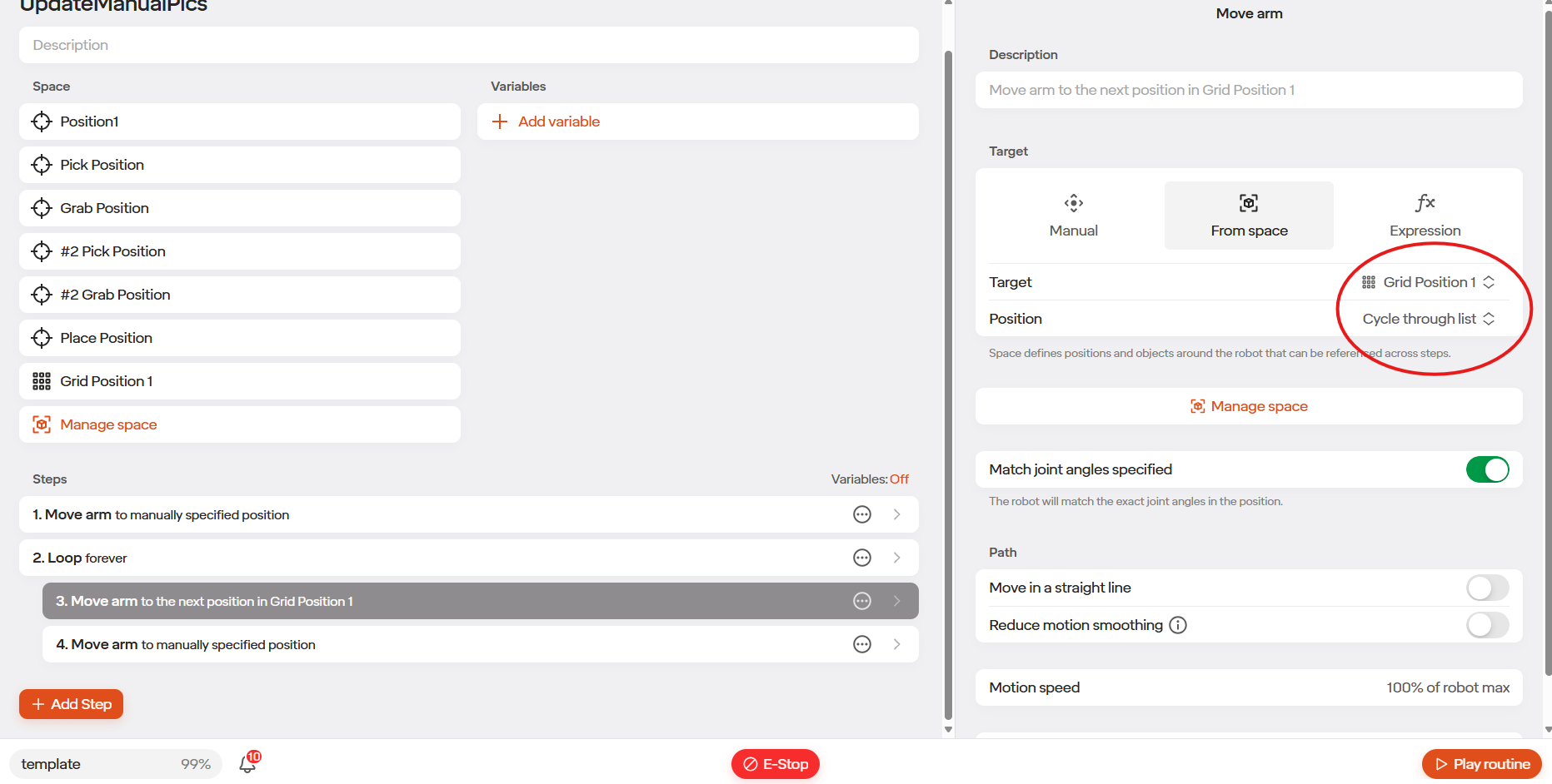
To use the grid, use a Move Arm command within a loop and select the grid within the “From Space” option. The robot will move to the positions in the grid, in order, each time the loop executes.
To program a grid with multiple layers, use an “Add Offset” to set an offset to the grid positions based on the number of times the loop has executed.
5.7.4 Freeform Position Lists
A Freeform Position List is a list of positions in an array. This can be useful when programming if you need to go to positions in order in a loop that are not in a grid, or indirectly address positions.
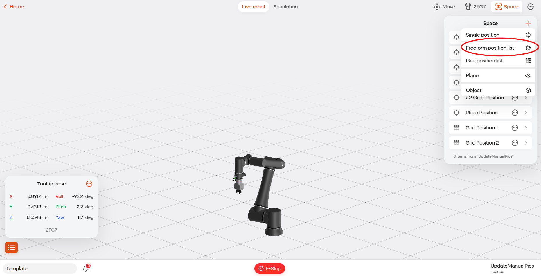
To create a Freeform Position List, go to the Move Robot area, go to the space (square icon), select the Plus icon, and then select Freeform Position List.
Give the position list a name.
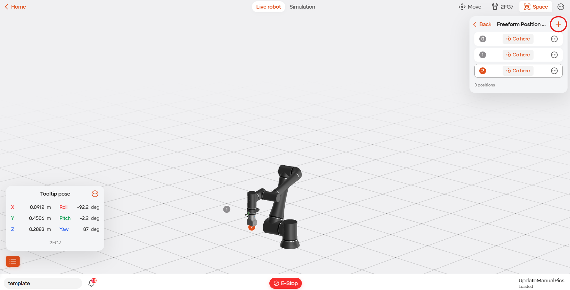
You can now drive to your first position using the Jog Robot functionality in the Move Robot view. Set the position. Repeat for the number of positions needed. Create the next position in the list using the “+” icon.
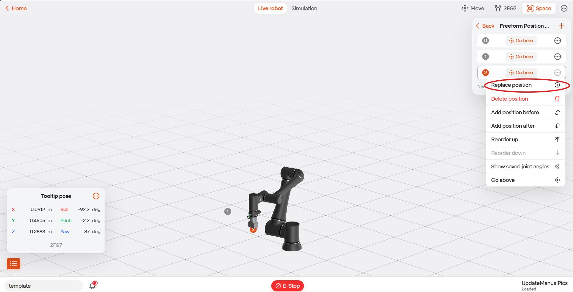
You can touch up the positions using “Go Here” and “Replace” (which is hidden behind the three dots icon). Once finished simply exit.
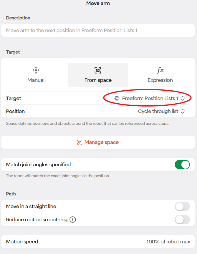
To go to the positions in order, use a Move Arm command and select the list from the Space.
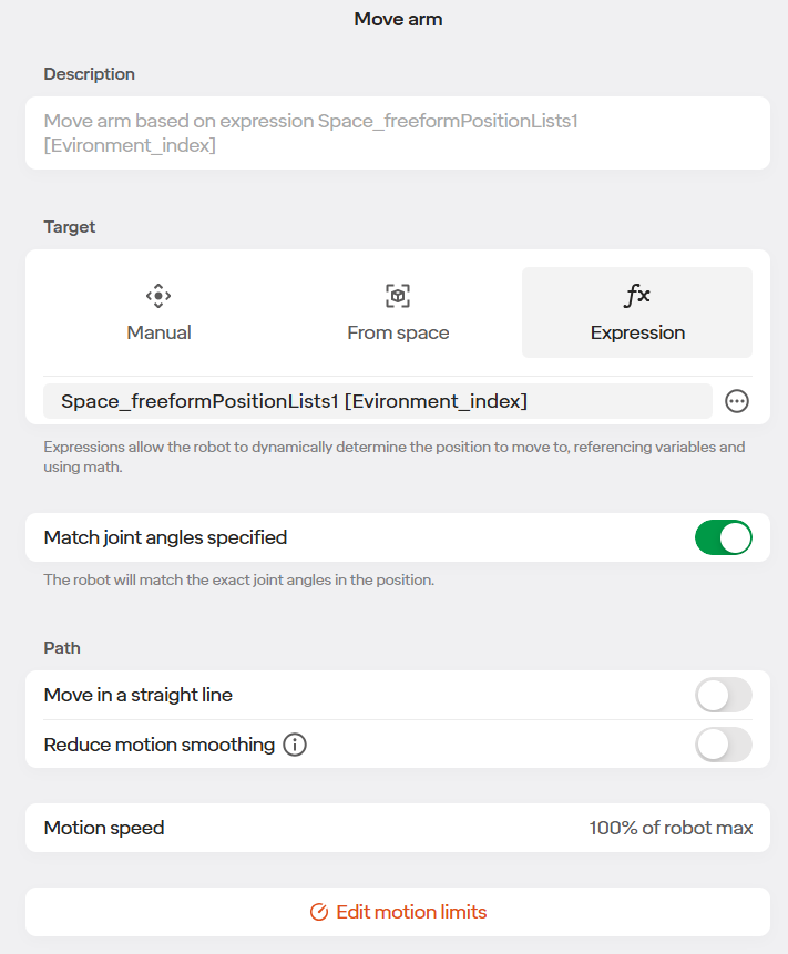
To access positions in the list not in order, use the “Expressions” option as shown. In this example we are going to the position in the list based off the environmental variable “index”.
5.7.5 Push Mode
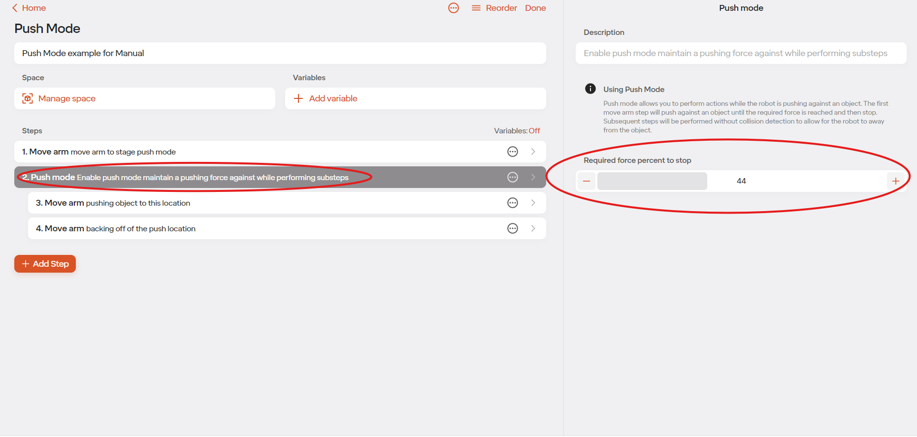
Push Mode allows you to perform actions while the robot is pushing against an object. The first move arm step will have the robot push against an object until the custom force requirement was reached. That step is finished once the force requirement is reached. Then the next step would be moving the robot away from the object. The steps are performed without the collision detection, allowing the robot to detect the needed amount of force.
Here is an example of implementing Push Mode into a routine:
Step 1 in this example is used to move the robot into the initial position to push the object.
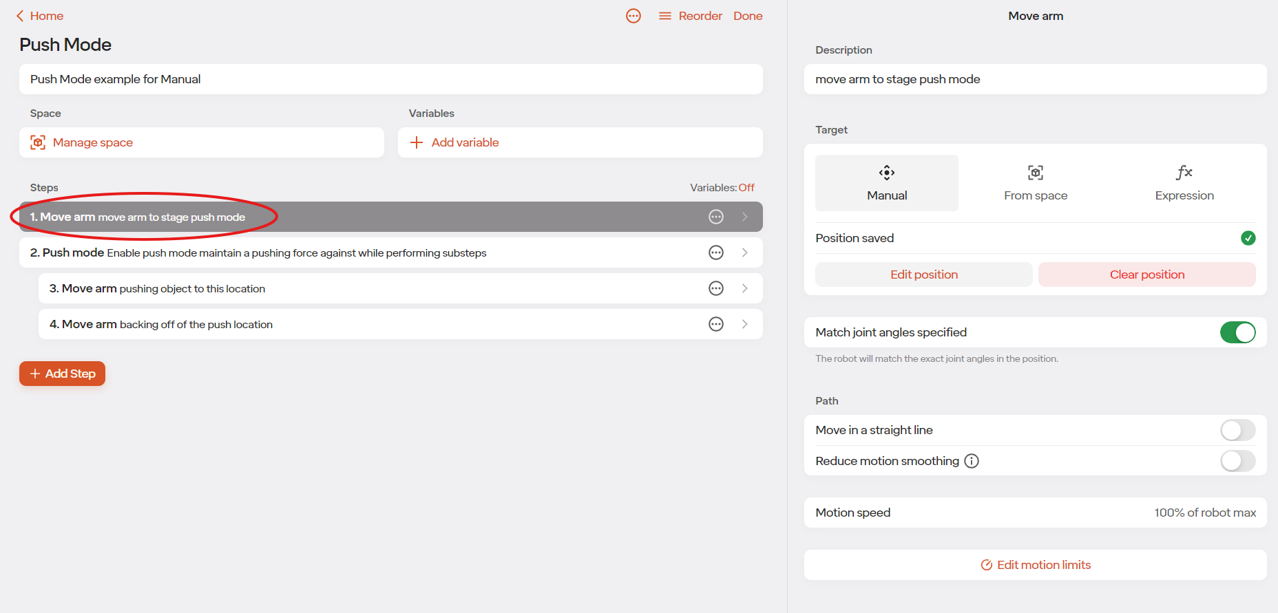
Step 2 in this example is enabling the push mode. Set the required amount of force for the robot to stop.
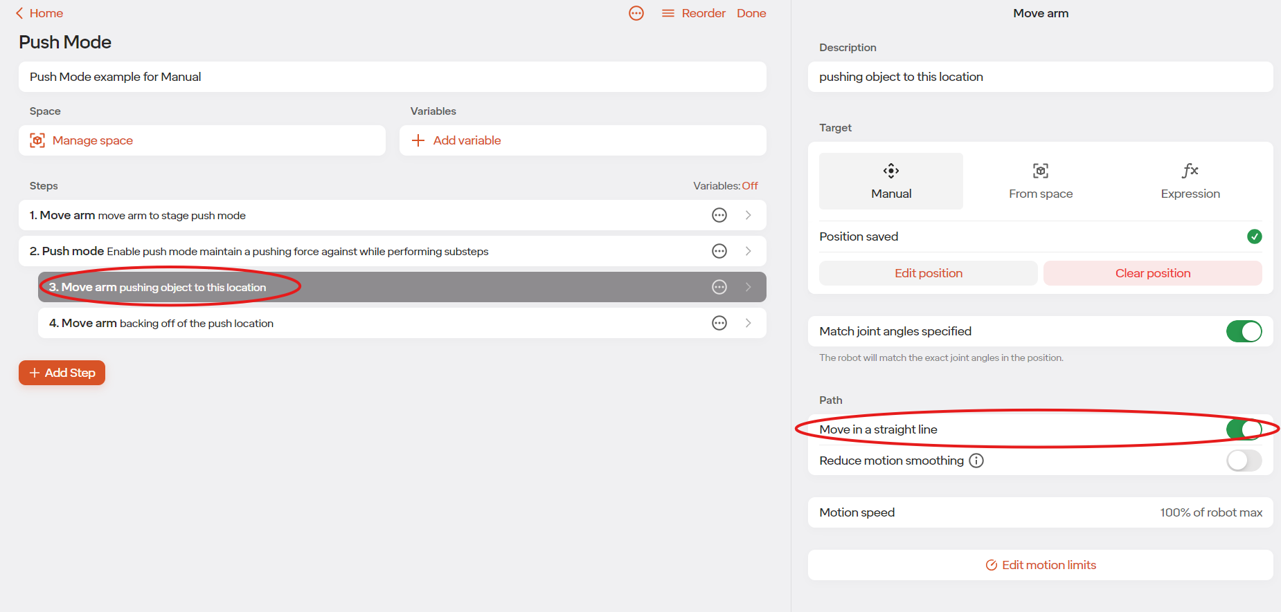
Step 3 in this example is the robot pushing the object to it’s final position. The robot will stop when it detects the selected force percentage. It is required that “move in a straight line” is selected for this step to work.
Step 4 in this example is the robot arm backing away from the object. This step is done still under Push Mode because Push Mode turns off collision detection. Once the routine is out of Push Mode, collision detection is back on and if the robot is still pushed against the object an error will happen. “Move in a straight line” will still need to be selected for this step.
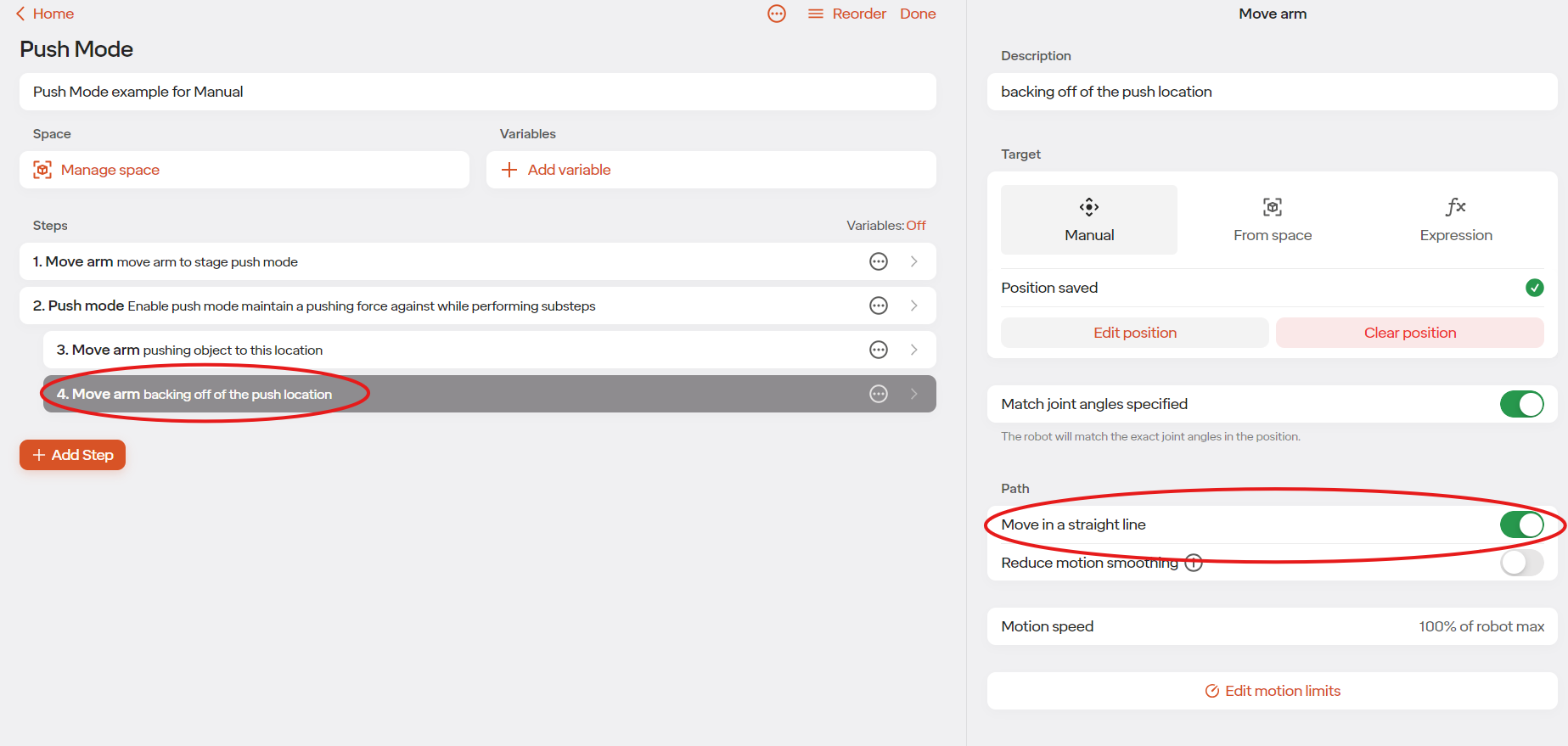
Once the robot is backed away from the pushed object, the steps after can leave Push Mode.
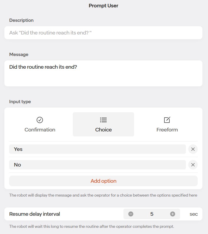
5.7.6 Prompt User
With the Prompt User step, the routine will pause and the operator will be prompted to take an action. Those actions are Confirm, Choice, or Freeform.
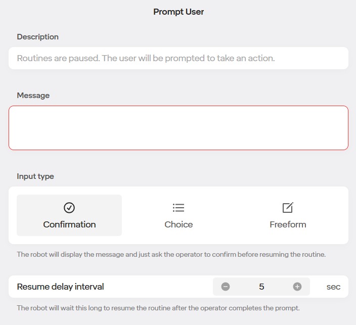
Each action allows you to add a message. The message will appear with the action when the routine pauses.
There is also a Resume Delay Interval. This is the amount of time the robot will wait to resume the routine after the operator has completed the prompt.
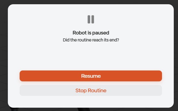
Confirmation:
When Confirmation is selected, the operator is given two answer’s respond with, “Resume” and “Stop Routine”. In the example image below, “Did the routine reach its end?” is the message that was written when editing the step.
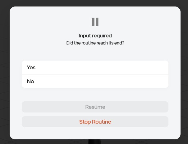
Choice:
When Choice is selected, you are able to add options for the operator to select. The examples in the image below are “Yes” and “No”.
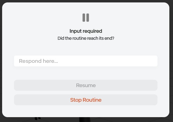
Freeform: When Freeform is selected, the operator has to enter a response in order to resume the routine.
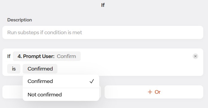
If Statements:
You are able to use the result of the Prompt User step in an If Statement. The Prompt User step can be used in the If Statement by “Variables” and then your Prompt User step.
When using Confirmation, you are able to choose between “Confirmed” and “Not Confirmed” in the If statement.
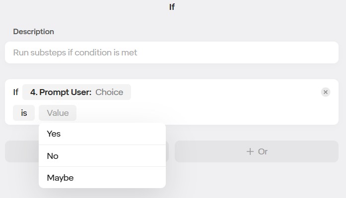
When using Choice, you are able to choose between whatever options you made in the Prompt User step (the options made in the example image are Yes, No, and Maybe)
5.7.7 Decision Logic
If Statement - Else If - Else:
To create branches and decisions in your program you can use the If / Else If / Else logic construction.
Add an If step to your program.
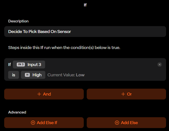
The IF statement has logic that when it evaluates to true will run more steps in your program inside the IF block.
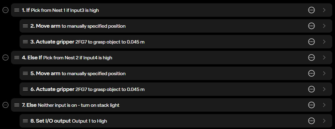
For more advanced logic you can add an Else by clicking the “Add Else” button. Any steps in the Else section are run if the initial IF is false.
For further functionality you can add one or more “Else If” sections by clicking the “Add Else If” button.
5.7.8 Machine Tending Application
5.7.8.1 Introduction:
Standard Bots offers machine tending solutions by the ability to add a CNC machine into your robot’s equipment. If you are using a Haas machine and are interested in using the Haas Ethernet Integration system, go to chapter 5.7.6.
5.7.8.2 Required components:
- Vices/vice adapters
- Robot end effector
- conveyors/feeders (if needed)
- loading/unloading stations
- Safety devices (if needed)
- Area scanners
- Light curtains and mirrors
- Safety rate start buttons
- Fence interlocks
5.7.8.3 Integrating CNC Machine:
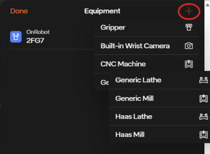
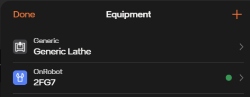
To add the CNC machine into your robot’s equipment, tap on the robot’s name at the lower left corner of the screen, tap the tab that’s labeled Equipment, then in the equipment tab press the orange plus icon in the upper right. Here you will see the list of the different CNC machines (general lathe, general mill, Haas lathe, Haas mill)
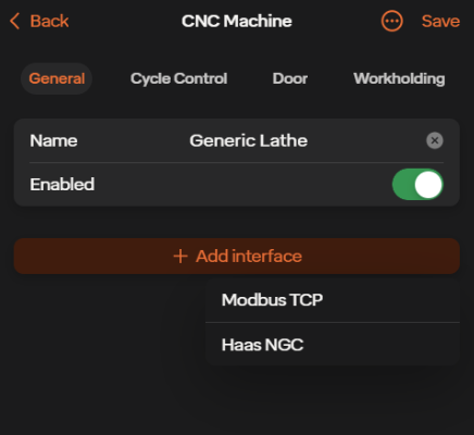
If you are using a generic lathe or mill, select the desired one. Once doing so you will be brought to the generals page. On the generals page you will be able to name your equipment, enable/disable your equipment, and add Modbus TCP and Haas NGC if desired.
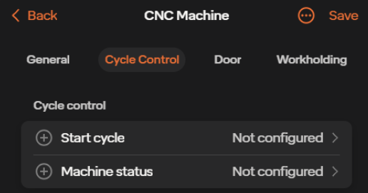
You can then select Cycle Control which can be seen on the top of the page. To tend a machine, the robot requires the ability to start the machine and to know when the machine is finished.
If the machine and the robot cannot be connected directly, these tasks can be accomplished by manually pushing buttons and by reading screens/lights with the robot’s camera.
In the Cycle Control page you will see Start cycle and Machine status.
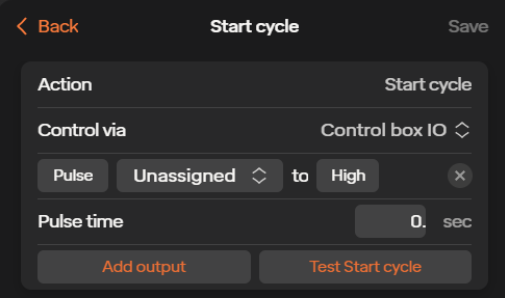
In the Start cycle page you will be able to choose which output or relay is used to start the machine’s cycle as well as if it goes high or low. You will be able to choose whether the output is set or if it is just a pulse. If pulse time is chosen you will also be able to choose the length of the pulse time. At the bottom of the page you can test the start cycle as well as add more outputs if needed. Make sure to save any changes in the upper right
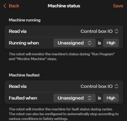
In the Machine status page you can set the inputs for machine running as well as machine faulting. For machine running, the robot will have assigned inputs which will monitor the machine’s status during its routine. For machine faulted, the robot can have assigned inputs which will monitor the machine for a fault status.
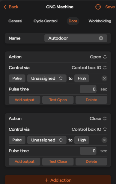
You can then backout and select the Door icon which can be seen on the top of the page next to Cycle control. Here you can set outputs which can control the opening and closing of the machine’s door. You will be able to choose whether the output is set or if it is just a pulse. At the bottom of the page you can add more actions if needed.
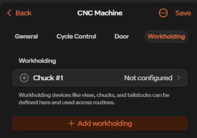
Next, in the Workholding page, you can set workholding equipment in your machine which the robot can send outputs to. At the bottom of the page you can add more workholding equipment if needed.
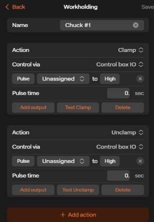
The actions for the workholding equipment are separated into Clamp and Unclamp. For each one you are able to choose the output from the control box, its state, and whether that state is a pulse or if it’s set. You are able to add more outputs to each action if needed. At the bottom of the page you can add more actions if desired.
When done, make sure to save your machine. Your machine will now be shown in the equipment tab. To make any new changes to it, simply click on your machine’s name.
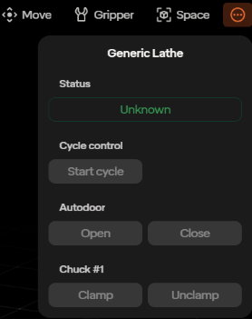
5.7.8.4 Accessing CNC Machine:
Once your machine is added to your equipment list, you are able to access it on your move robot page. Once there, go to the three dots icon in the upper right corner of the page and select your machine.
Here you can see the status of your machine, as well as the ability to start the cycle, open and close the doors, and open and close your workholding equipment.
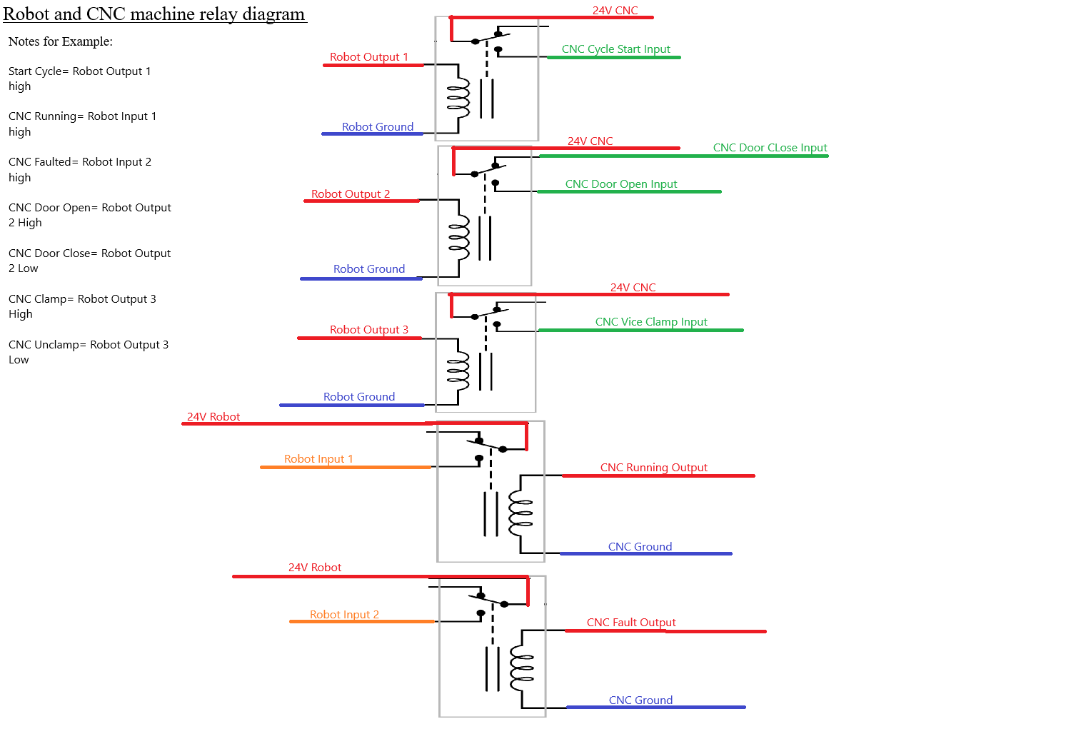
5.7.8.5 Wiring Your Robot Control Box to a Generic CNC Machine:
If you are using a generic CNC machine then you will have to hard wire your robot’s control box to your CNC machine. This will be done by utilizing your control box’s and CNC’s inputs and outputs. And due to both machines being on separate commons you will need the use of relays in order for them to successfully communicate with each other.
Here is an example of how to connect you robot’s control box to your CNC machine with the use of relays:
5.7.8.6 Creating a Routine- Generic CNC Machine:
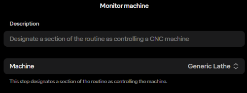
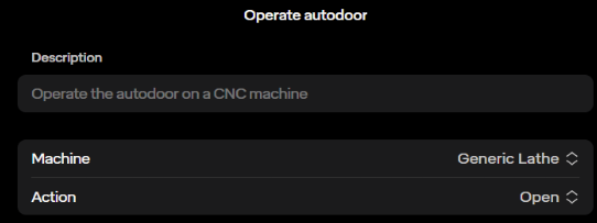
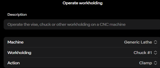
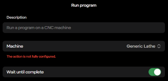
In the routine editor page you can find tasks that are made for a machine tending routine. These steps are: Monitor Machine, Operate Autodoor, Run Program, and Operate Workholding.
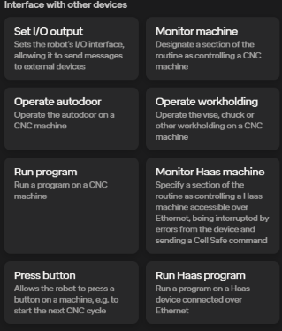
For the Monitor Machine step, you are able to choose the machine you created earlier. You dedicate this section of the routine to controlling your machine.
For the Operate Autodoor step, you can select the machine, as well as choose the action you want to perform with the door (open or close).
For the Operate Workholding step, you can select the machine, the workholding piece, as well as choose the action you want to perform with the workholding equipment (clamp or unclamp).
For the Run Program step, you are able to select your machine that you wish to run. You are also able to choose whether you want the robot’s routine to pause until the machine is done.
5.7.8.7 Creating a Routine- Haas Machine:
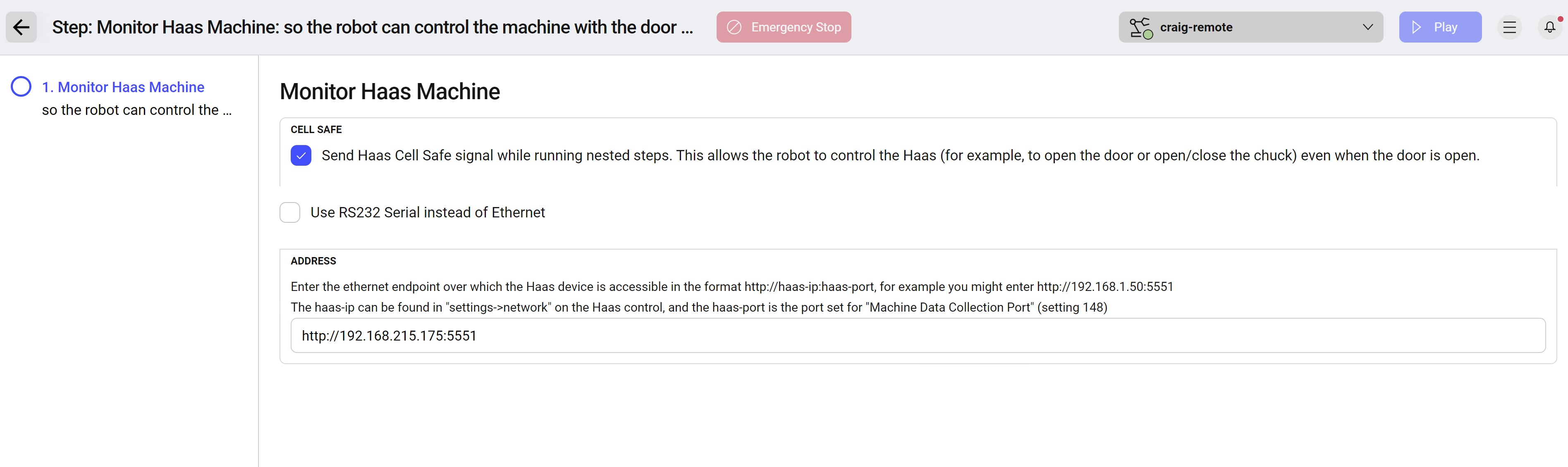
There are also Haas specific steps you can use if you are using a Haas machine. These steps are Monitor Haas Machine and Run Haas Program.
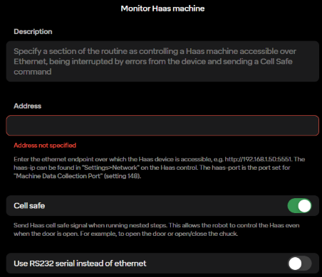
The Monitor Haas Machine step specifies a section of the routine to control the Haas machine. Here you have to enter the ethernet endpoint for the Haas. Here you can also choose whether you want Cell Safe on and if you’d rather use RS232 serial instead of ethernet.
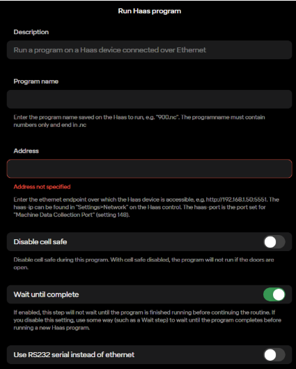
The Run Haas Program step runs a program on the Haas machine that’s connected over ethernet. Here you will have to enter the program name for the Haas to call (ex: 900.nc). You will also have to once again enter the ethernet endpoint for the Haas. You can choose if you want Cell Safe on, to wait on this step until the Haas is complete, and if you’d rather use RS232 serial instead of ethernet.
5.8 External IP Communication
5.8.1 Haas Ethernet Integration
5.8.1.1 Introduction
For Haas machines that support Next Generation control (generally 2017 or newer machines) Standard Bots provides a first-class integration suite that allows for ethernet communication between the Standard Bots robot and Haas machine. This allows for quicker setup and more flexibility with less wiring.
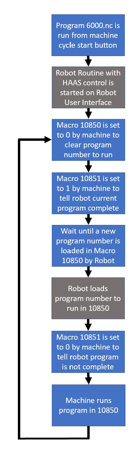
Standard Bots provides a set of sample .nc files to get started with an ethernet Haas integration. The integration works by running a main program on the Haas machine (in the example this program is 6000.nc). It then uses Macros 10850 and 10851 to complete handshaking between the Haas machine and Standard Bots robot as shown below:
Please be sure to review the comments in the sample code. G103 P1 is a required step in the 6000.nc main sample code to ensure the integration that happens through the macros functions correctly. Do not remove this step. If needed, add a G103 P0 as well as several empty lines after to the beginning the machine programs you create to run from the robot (called through macros from 6000.nc) to re-enable lookahead during those programs and ensure the fastest program speed. A P0 will disable block limiting, allowing the machine to look ahead as much as it wants. A number option will limit the number of blocks to look ahead.
5.8.1.2 Requirements:
- Haas machine with Next Generation control
- Network connection between machines (Either Wireless or Wifi)
- The “Cell Safe” signal must be held high using the “Monitor Haas
Routine” step anytime the door is open. If the signal is dropped with
the door open the Haas machine will go into Feed Hold and will need to
be reset and then cycle start must be hit on the Haas again.
- HAAS sample programs located at: https://docs.google.com/document/d/1HYtyWCjeHh6-LjbQF4H48BQuOi488yxzRS0UnXByHUY/edit?usp=sharing
- Haas Test Schema locate at: https://docs.google.com/document/d/1br955z71rnvLtPXpn5ElDZ-FGeQi1ostgo20YAXcXaY/edit?usp=sharing
5.8.1.3 Network Configuration:
In order to ensure a reliable solution the network between the robot and Haas machine must be configured correctly. Setting a static address without consulting the router/network configuration can cause duplicate IP addresses and other issues which will result in the robot not being able to run the Haas programs remotely. The Haas machine must have a known set IP address reachable by the robot for the integration to work through power cycles. There are several acceptable methods to setup a network between the robot and Haas machine:
- Configure the Haas machine on a wireless network. The IP address
must be set to static on the machine with an address outside of any DHCP
range or must be configured to always have the same IP address through
the router configuration.
- Configure the Haas machine on a wired network with router. The IP
address must be set to static on the machine with an address outside of
any DHCP range or must be configured to always have the same IP address
through the router configuration. Allow the robot to DHCP through the
network router.
- Run a single cable between the robot and Haas machine. The Haas machine must have a static IP address set manually. Contact Standard Bots Support for assistance setting a static IP address on the robot on the same subnet as the Haas machine.
5.8.1.4 Integration:
Ensure program numbers 6000.nc-6005.nc are available on the Haas machine.
Load Standard Bots sample NC files onto the Haas machine.
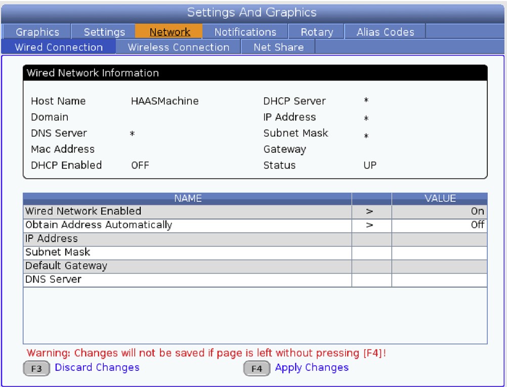
If using a wired connection, run an ethernet cable from the Ro1 cabinet to the Haas machine cabinet. The ethernet port on the Ro1 box is on the underside of the IO connection points in the box. The ethernet port on the Haas for Machine Data Collect is usually on the upper left when looking at the back of it. To get to the ethernet settings on the Haas navigate to Settings→Network→Wired/Wireless Connection.
Set the Haas machine up to communicate with the robot. The robot and Haas machine must be on the same subnet (3rd set of numbers in IP address) and be on the same wireless or wired network to communicate with each other. To ensure Haas can talk to the robot even through a power cycle the Haas must be set to a static IP address (no DHCP) or have network provisions made to ensure it is always the same IP address.
Enable machine data collect on the Haas (settings 143) and set the port to 5551.
If you are using a wired connection without DHCP, use the Standard Bots tablet application to set the IP address. You may need to log out of the User Interface by going to robot name menu in the bottom left then selecting Logout.
Load the sample “haas test” program provided by Standard Bots into the routine editor by going to Actions-> Edit Routine Schema and pasting the contents of the text file in. Then select “Create Routine”.
Edit the first step of the sample routine. Leave the “Send Haas Cell Safe” button checked. This allows the robot to run routines with the door open, which is often required (IE, when you need to close the door).
Update the IP address of the Monitor Haas Machine step to match the IP address of the Haas. Ensure the port remains at the end of the address. The format is: http://xxx.xxx.xxx.xxx:port . I.e., http://192.168.215.175:5551. Save the step.
Go back and edit Step 4, Run Haas Program.
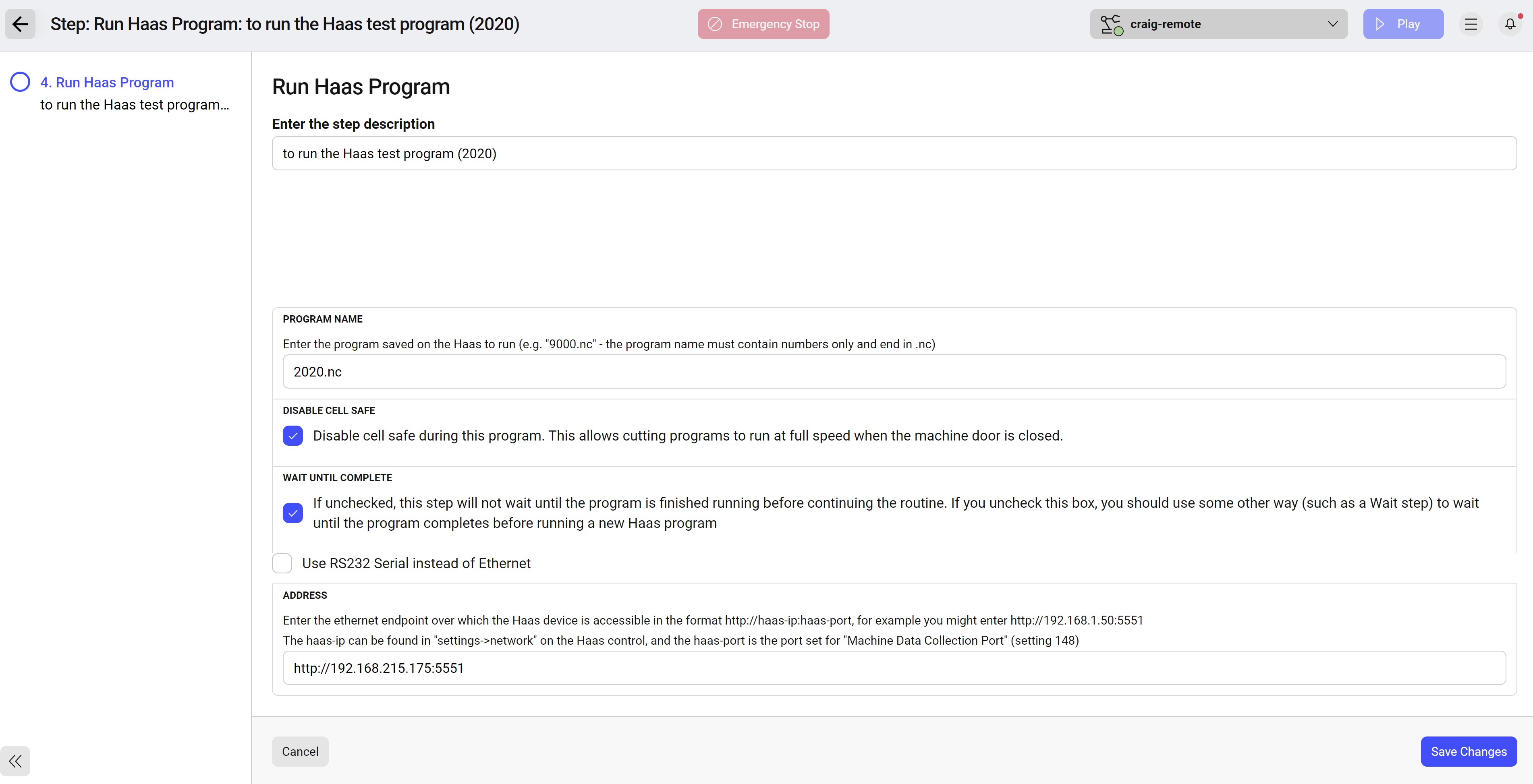
The “haas test” program will attempt to run 2020.nc. In many Haas machines, this is the spindle warmup program. If needed, change this program number to a different program under “Program Name”.
Leave “Wait until Complete” checked. This will ensure the routine stays at the current step until the Haas has completed the program sent above under “Program Name”.
Update the IP address of the Monitor Haas Machine step to match the IP address of the Haas. Ensure the port remains at the end of the address. The format is: http://xxx.xxx.xxx.xxx:port . I.e., http://192.168.215.175:5551. Do not use 127.0.0.1 as that is the default loopback address. Save the step.
Start program 6000.nc on the Haas using the standard cycle start button on the Haas.
Start the sample program on the robot by running the routine.
The spindle warmup program (or alternative program chosen above) should now run. If it does not work verify the 10850 macro variable on the Haas is updating to the program number you put in the Run Haas Program step. If it is not, verify communication between robot and machine. The Haas machine must be running the 6000.ns]c program with no errors first, then you must start the robot program.
5.8.2 Modbus/TCP Client
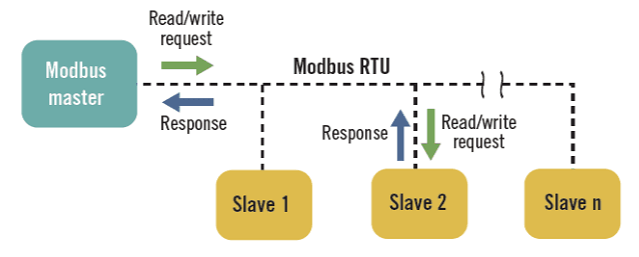
One way for the robot to communicate with other devices is through Modbus, one of the oldest and most widely used communication protocols in industrial settings. Modbus provides a common language that enables different devices to communicate with each other, allowing devices from different manufacturers to work together. A Modbus Controller initiates communication and manages the data exchange between the compatible devices.
Modbus can operate over various physical layers, including serial communication methods like RS-232, RS-485, and RS-422, as well as Ethernet. Modbus TCP allows Modbus communication to occur over TCP/IP networks, enabling it to coexist alongside other Ethernet protocols.
Please note: the robot is the client/master, so it would need to connect to the server/slave.
5.8.2.1 Setting up Modbus
Utilize the following steps to setup Modbus.
Step1) To setup Modbus communication with your RO1 click on the menu in the bottom left corner and select equipment.
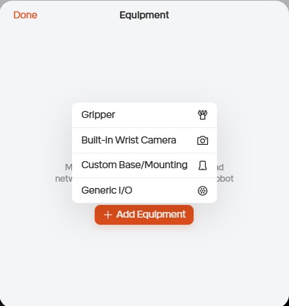
Step 2) Click on add equipment, generic I/O, Modbus TCP Client.
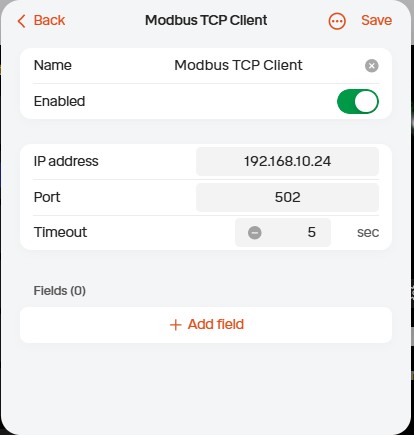
Step 3) Provide a Name for the Modbus TCP Client, IP Address, Port #, and Timeout.
Note: For this demonstration we will be using an IP address of 192.168.10.24, Port 502, as well as a 10 second timeout. This will vary based on your application.
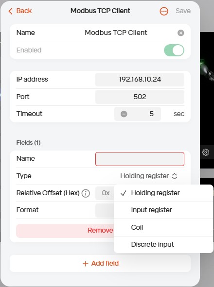
Step 4) Click on add field and select the field type you would like to use. You can choose from the following types: Holding Register, Input Register, Status Coil, or Input Coil.
Note: For this demonstration we will be using a Holding Register.
Step 5) Provide a name for your field. When complete click save in the top right corner.Note: For this demonstration we will be naming the Field HR1 as we will be setting up a holding register. The offset will also remain zero for this demonstration.
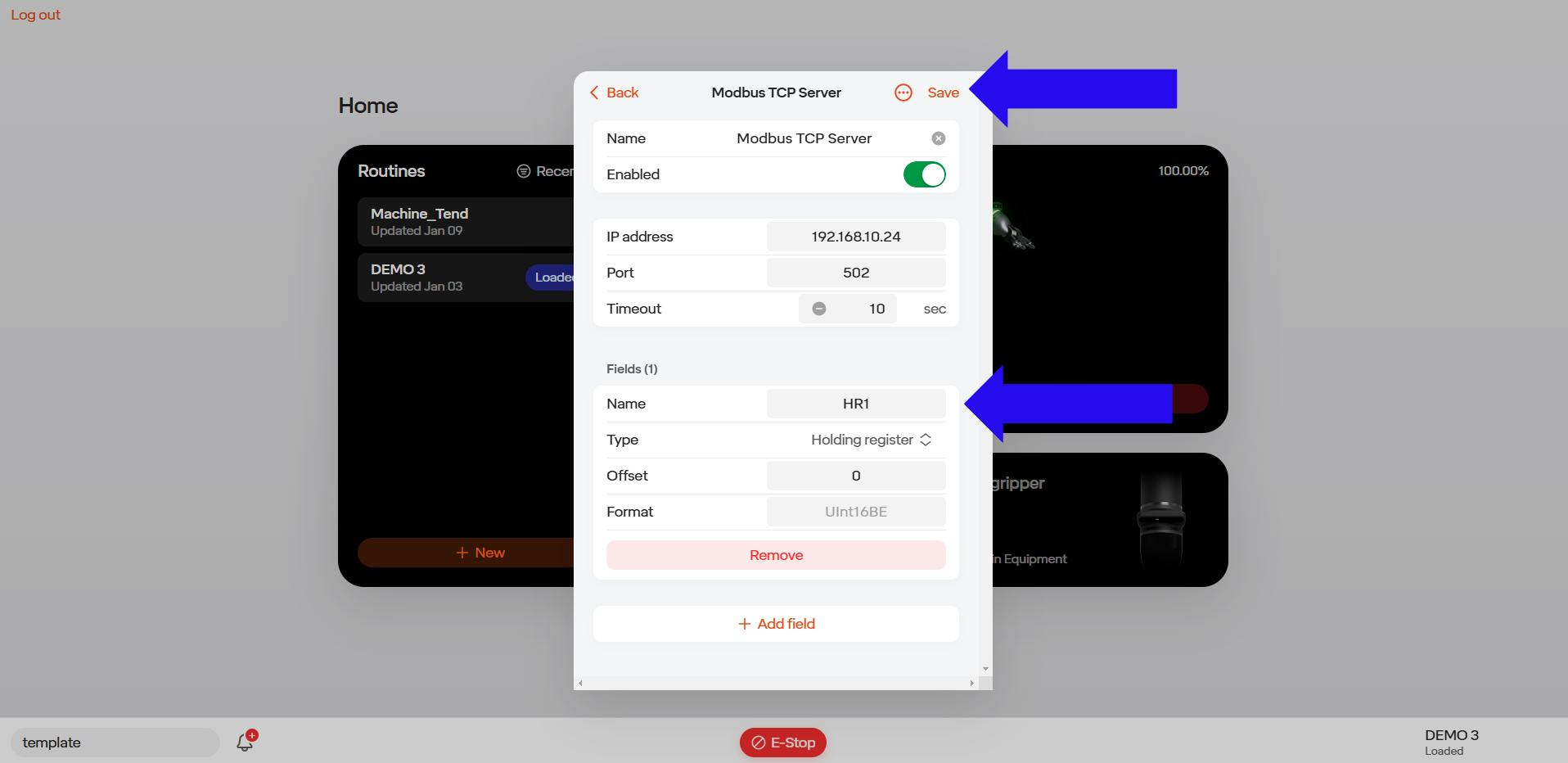
Note: To add additional fields repeat steps 4 & 5 as desired.
Step 6) Once you have selected save you should see your modbus tcp client added to the equipment list.
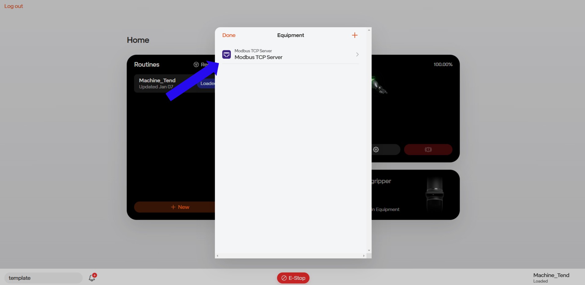
Step 7) Once you have added a Modbus TCP Client to your equipment you can now utilize it in a routine. Open up the routine and add a new step. Select “Network Request”.
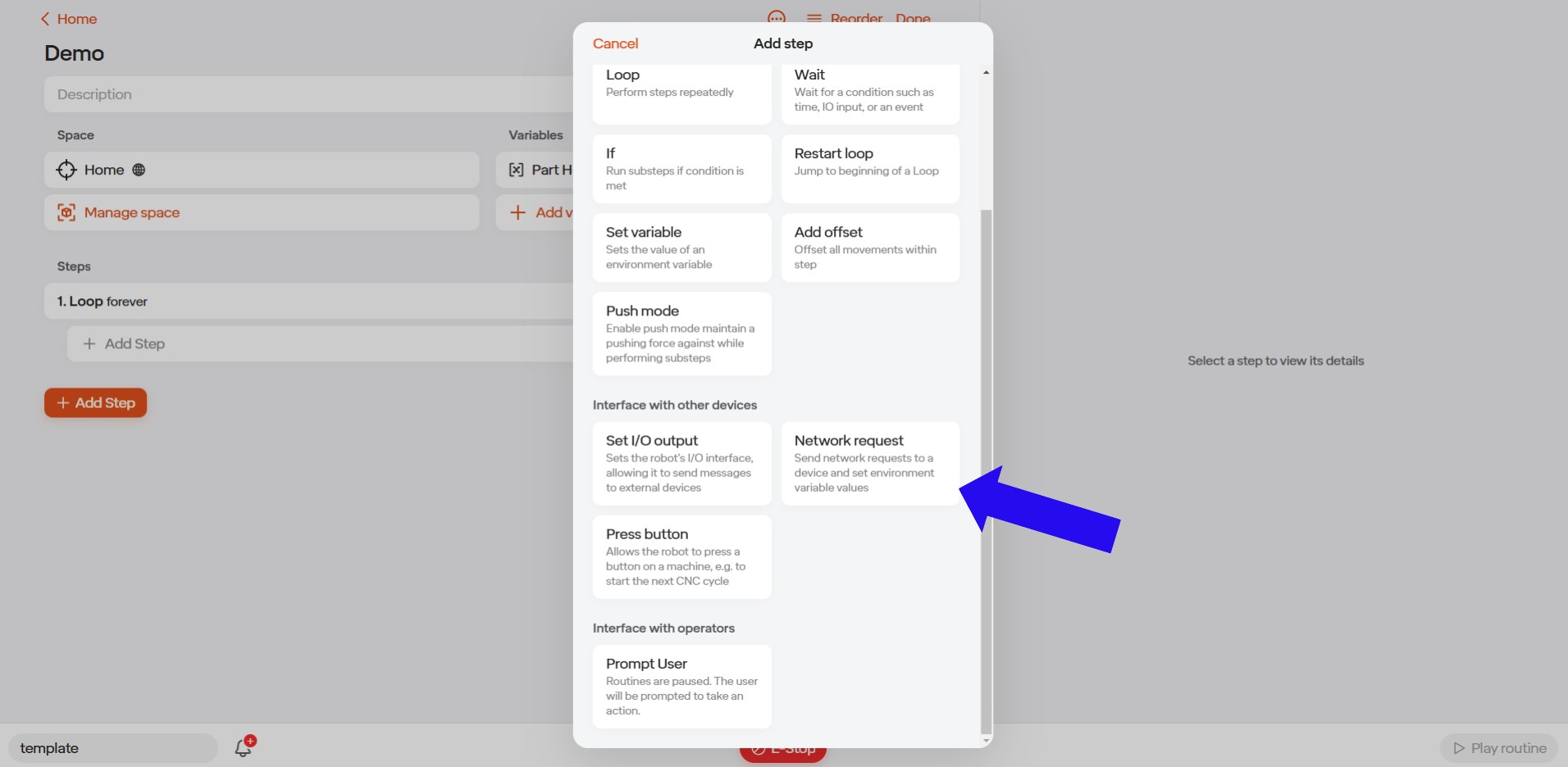
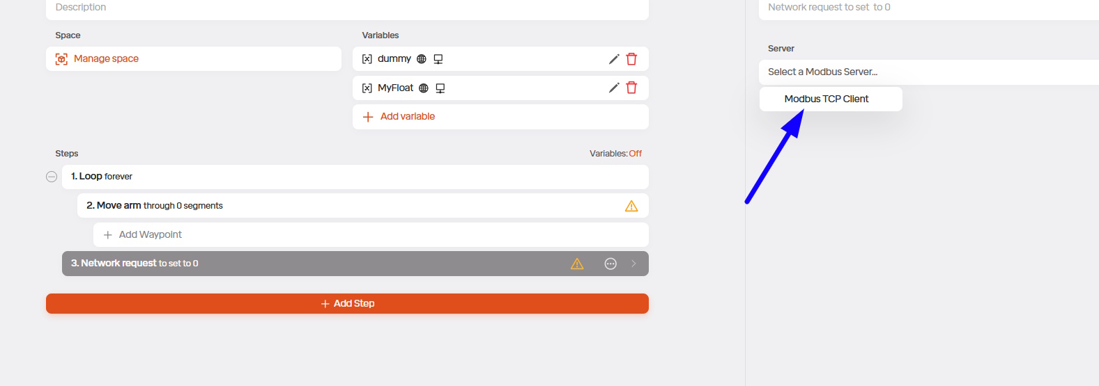
Step 8) Select which Modbus Client you would like to use.
Note: For this demonstration only one modbus client has been set up.
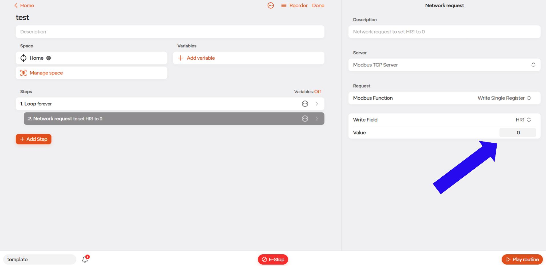
Step 9) Select the type of Modbus function you would like to request. The user can select either Read holding register or write single register.
Note: For demonstration purposes we will be selecting “Write Single Register”.
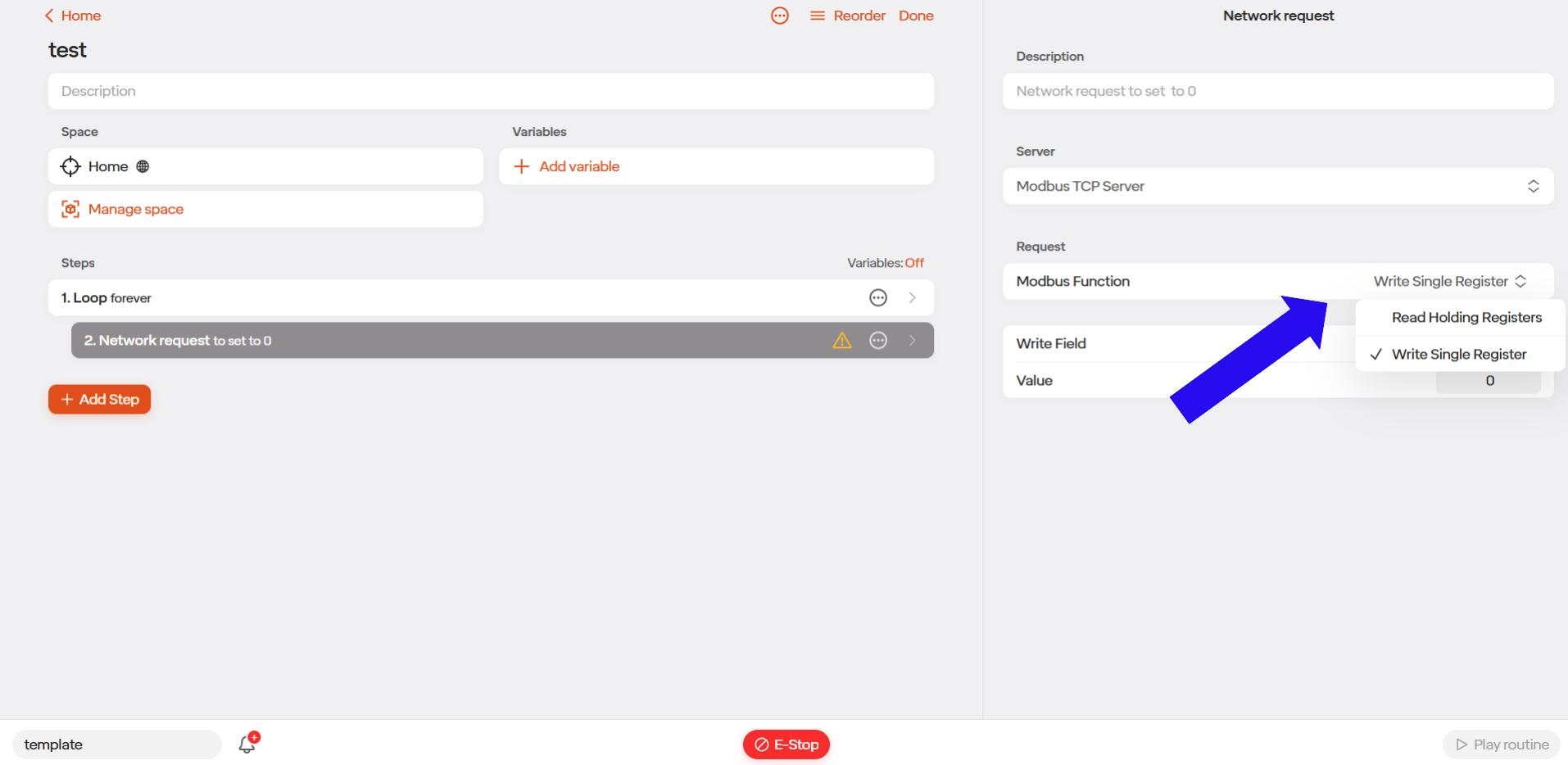
Step 10) Select what field you would like to write to, and what value you would like to write.
Note: HR1 was selected this was setup in step 4 & 5 We will be writing a value of 0 to HR1. This will be used to tell the external device that we are done with a particular step.
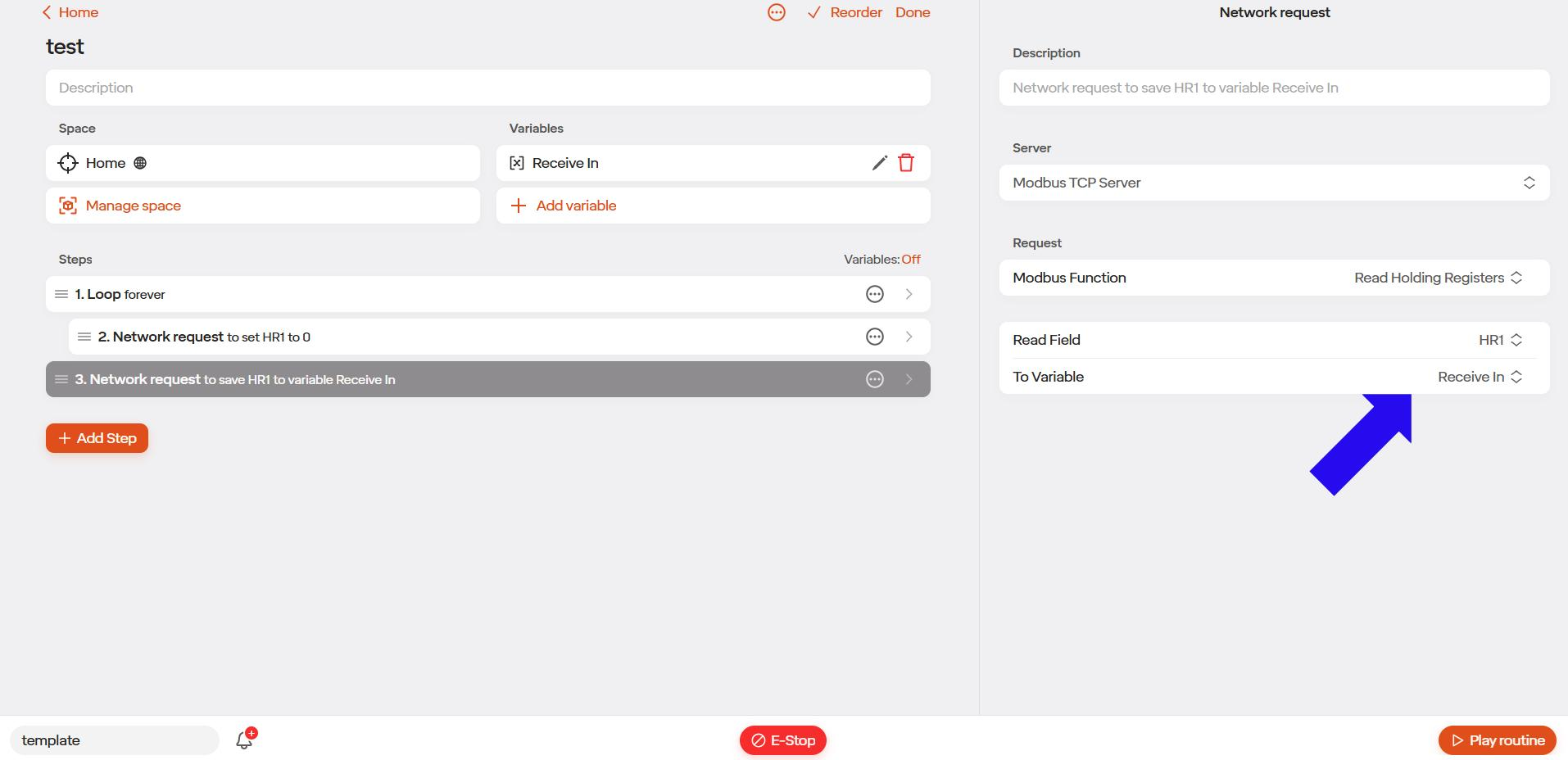
Step 11) Next we will repeat steps 7,8,&9 however this time we will setup a read holding register request. Our read field will be HR1 and we will want this to be sent to our “Receive In” variable.
Note: See Creating a Global Variable section for setting up variables.
5.8.3 Modbus Routine Examples
5.8.3.1 Reading from a Register Example
Note: This example demonstrates how Modbus can be employed to read a value from a single register and assign that data to a variable within the routine for subsequent use or decision-making. This approach proves beneficial later in the routine, as the value of the “vice status” variable can be leveraged to inform critical decisions.
Summary: Step 24 illustrates the process of reading the holding register, h1, following the closure of the vice in Step 22. The retrieved value is subsequently assigned to the Vice Status variable, as highlighted in Figure 1. Note: Vice status variable was setup prior to adding the network request step.
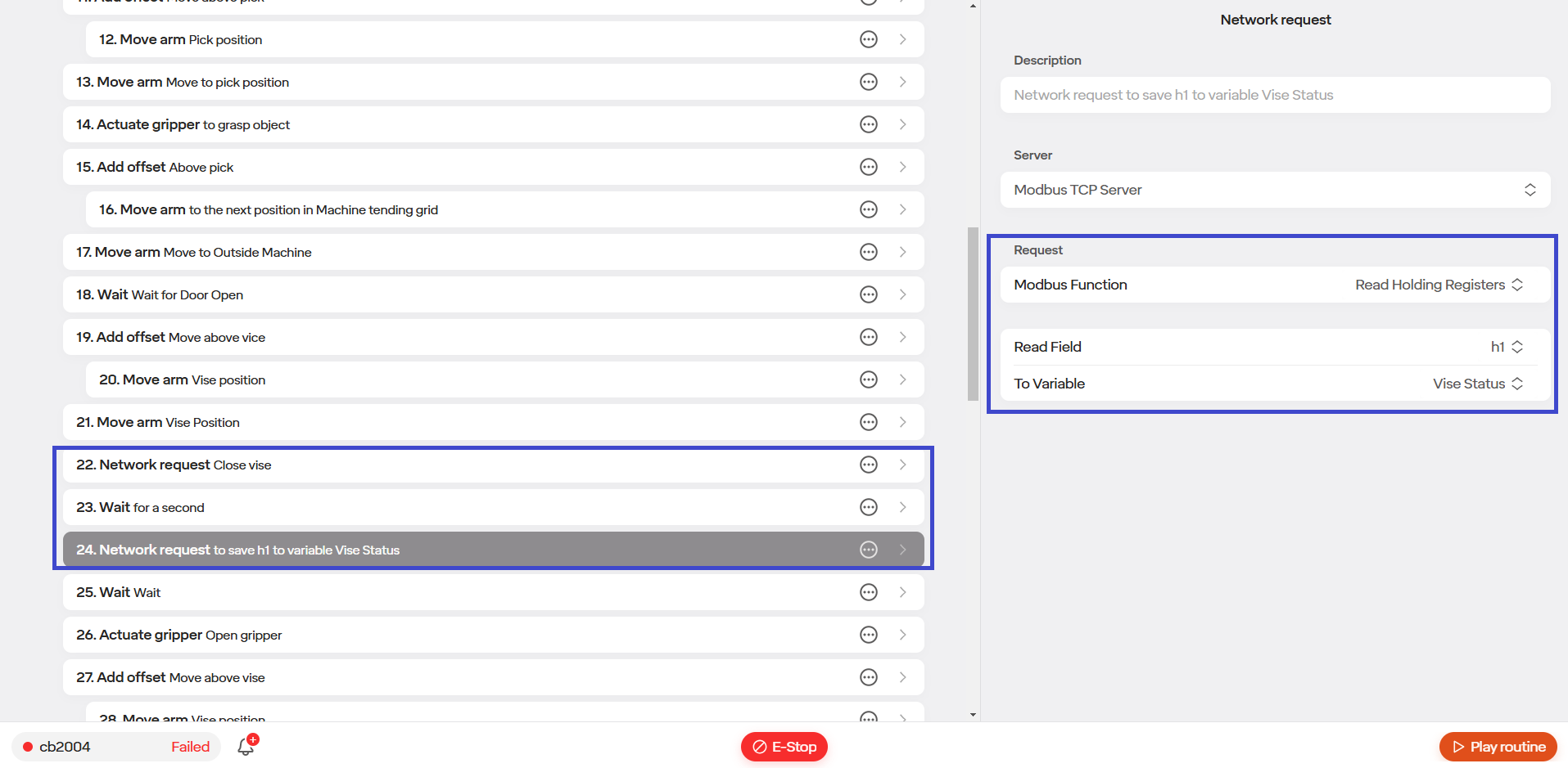
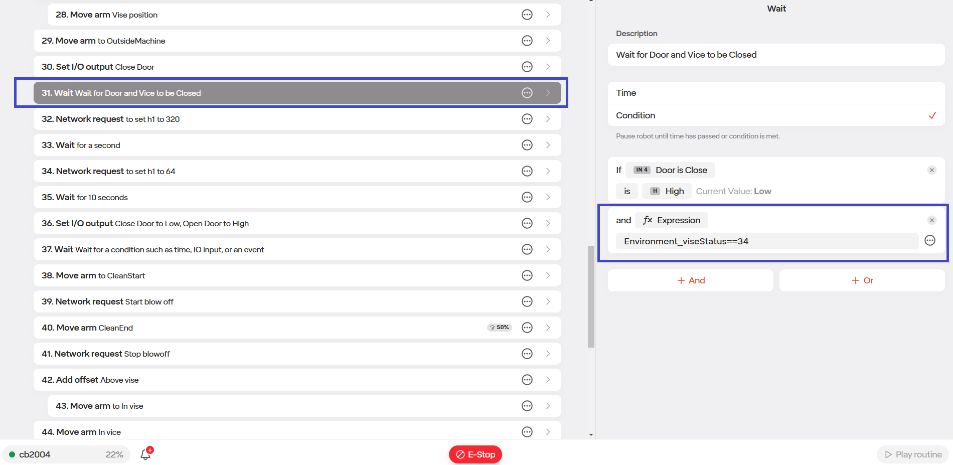
The retrieved value is then utilized in Step 31, in which the program is looking for the CNC Machine Door and Vice to be closed before continuing. For purposes of this example the value of 34 is used to indicate the vice is closed. This can be seen in Figure 2.
5.8.3.2 Writing to a Register Example
Note: This example illustrates a machine tending application, where Modbus is utilized to write a value to a single register for controlling an air blow-off nozzle mounted on the end effector. The primary function of the blow-off tool is to remove any debris from the part before the robot proceeds to pick up the finished component.
Summary: Steps 38-41 illustrate the process of writing a value to a holding register within a routine. This is clearly highlighted in Figure 1.
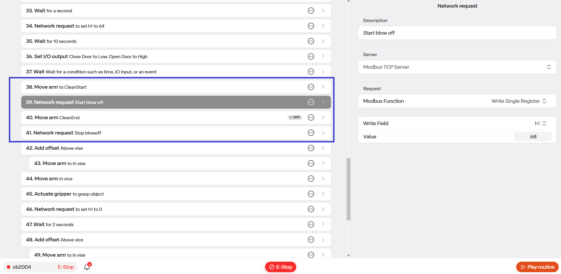
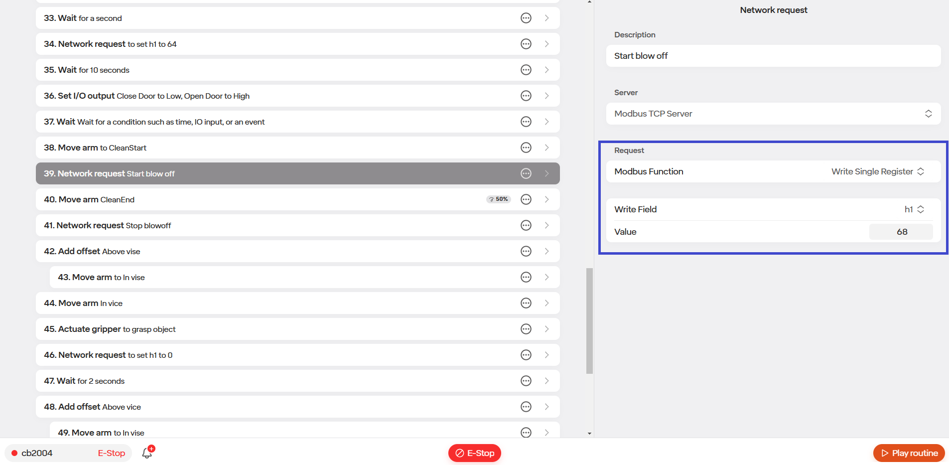
In step 39 a value of 68 is written to the holding register, h1, to turn on the valve for the blow off tool. This can be seen in Figure 2.
The robot arm then moves to its end location in step 40.
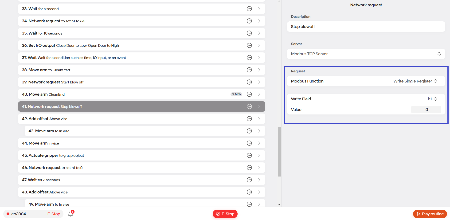
In step 41 a network request is then made again to shut the valve for the blow off tool off again. This is accomplished by writing a value of 0 to the holding register h1. This can be seen in Figure 3 below.
5.9 API
All APIs should be treated as Beta software. While software that is controlling the robot through the API is being developed the robot should be safety guarded as a mistake in the software being developed can result in unexpected motion. Access to the API is granted on a case by case basis. Please contact [email protected] to discuss access to the API.
5.9.1 Python SDK
The Python SDK lets you control and communicate with the robot using your own Python code. It gives you access to tools and commands for things like moving the robot, reading sensor data, and connecting to other systems like cameras or cloud services. This is good for users who want more flexibility, whether you’re building custom applications, automating tasks, or adding new features beyond what the built-in interface can do.
You can access the Python SDK by going to API Docs | Standard Bots and selecting Python SDK.
Once there you will be brought to the SDK configure page where it will guide you through installing the SDK and how to create a connection.
5.9.2 REST API
With REST API you will be able to control the movements of your robot. Leverage reference frames, tooltips, and more to accomplish your task.
You can access the REST API by going to API Docs | Standard Bots and selecting Move Your Robot
You will then be brought to the Arm Movement and Position Control Page. Here it will walk you through moving the robot via the API.
5.9.3 ROS2
With ROS you will be able to use fine grained controls and force feedback. At this time for ROS2, the level of control possible is Joint Trajectory Controller and Tooltip Pose in beta. ROS Nodes are not available at this time through the Standard Bots UI. ROS2 is not required for basic applications. The cobot can run predefined programs without ROS 2. ROS 2 is only needed for custom applications, integration with external systems, or advanced programming. Please reach out to learn more as this is in Private Beta.
To set up the ROS2 API, follow the steps on Notion: ROS2 API Runbook (Notion) To write Standard Bots ROS2 Python programs, follow the steps on Notion: ROS2 API Python Scripting (Notion)
The URDF is located here: RO1 URDF File (Notion)
5.10 Global Space & Variables
5.10.1 Introduction to Global Space Items.
(Note: section was written using software update version main 4608.)
The following section defines and explores use cases for global space items as well as global variable items.
5.10.1.1 Global Space Items
Global space items allow users the ability to access a saved robot position in space across all routines.
5.10.1.1.1 Types of Spaces
- Single Position
- Freeform Position List
- Grid Position List
- Plane
- Object
5.10.2 Creating a Global Space
Note: for this example we will be making a single position global.
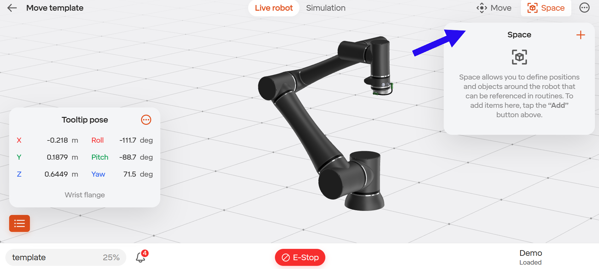
Step 1) In your routine click on “Manage Space”
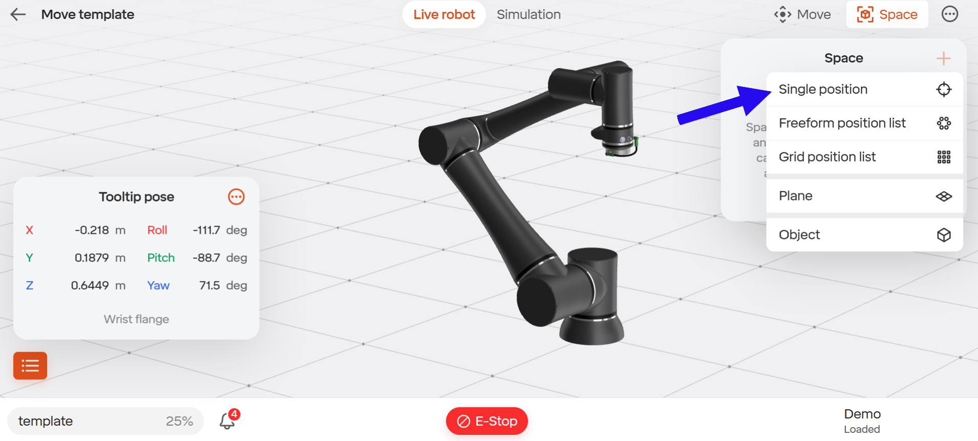
Step 2) Move the robot to the desired position and select “+” from there you will be prompted to choose the type of space you would like to add.
Step 3) Click “Single Position”
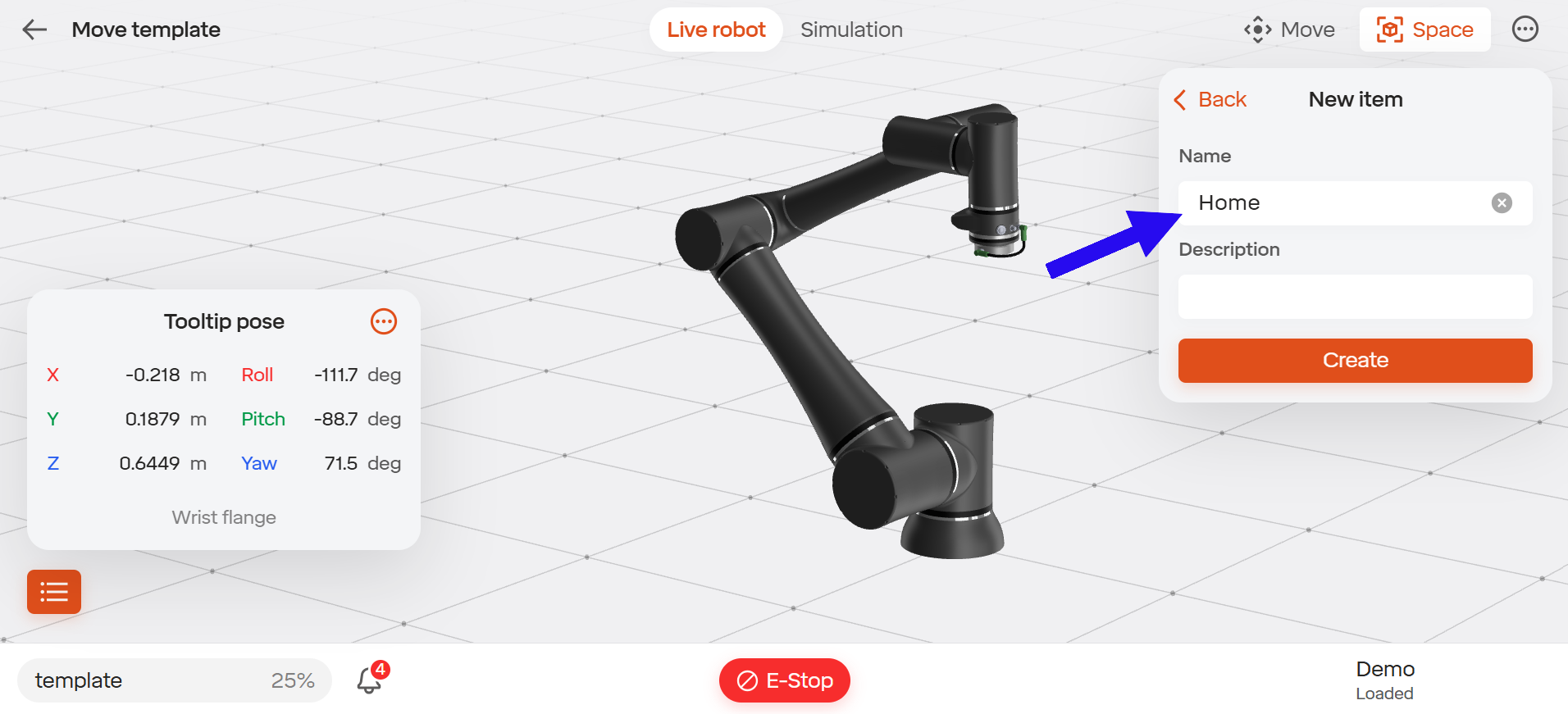
Step 4) You will be prompted to name your position. (For this example we will name the position “Home”.)
Step 5) After naming the space you will be asked to set its position.
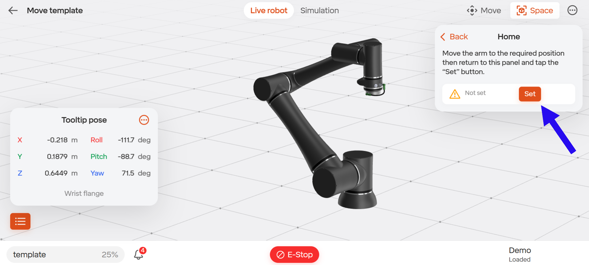
Step 6) Confirm the position was set, indicated by a green check mark that will appear on the left hand side.
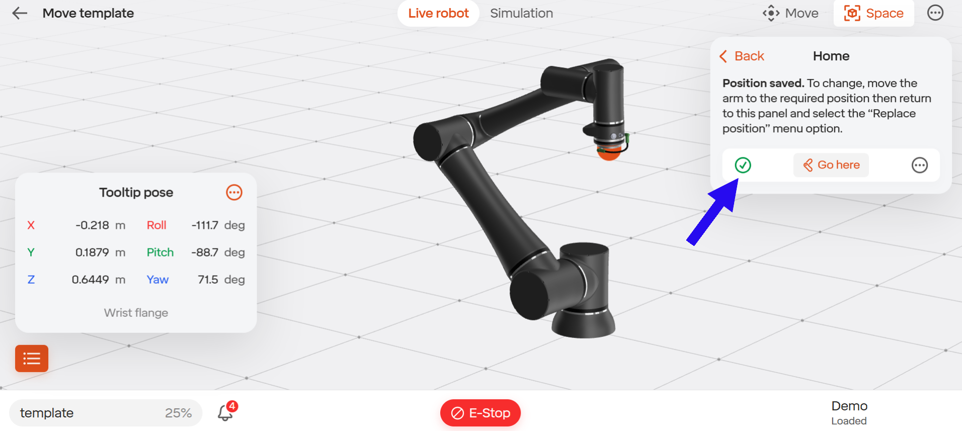
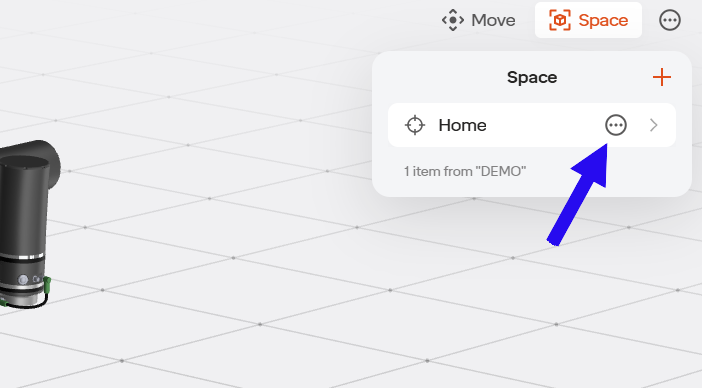
Step 7) Once the space has been set, hit BACK found in the top right corner. This will take you back to the main space menu. Once you have returned to the main space menu, locate the space you would like to make global and click on the options for that space. The options button will be indicated by the ellipsis menu icon.
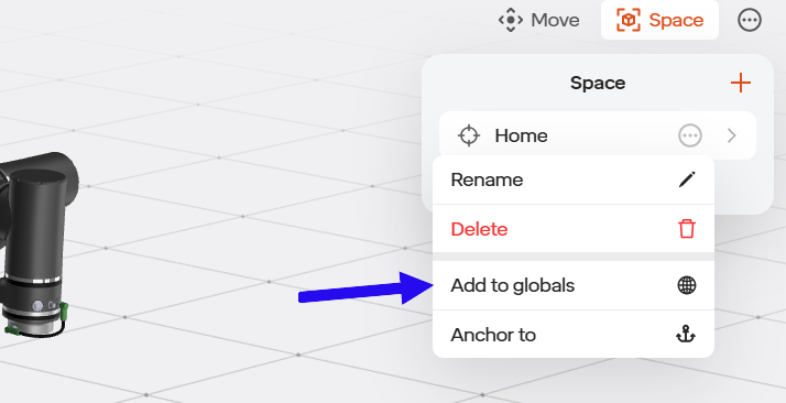
Step 8) Once in the menu drop down select “Add to Globals” and this space will be able to be accessed across all routines.
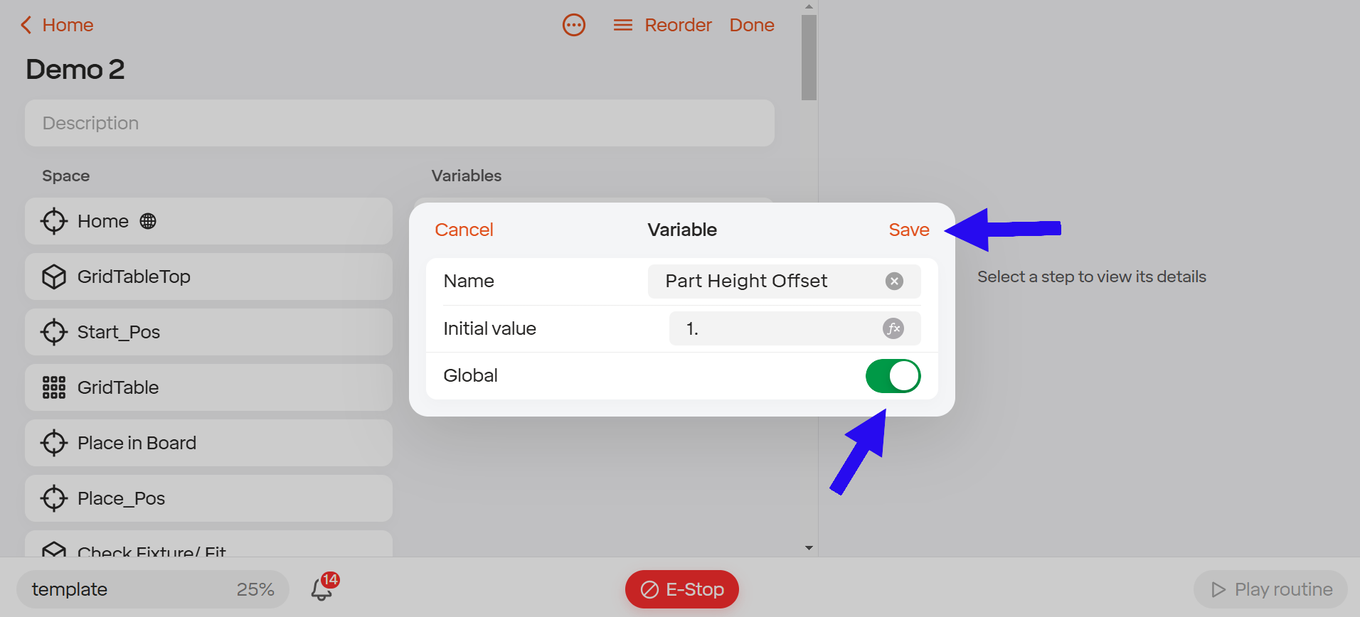
5.10.3 Creating a Global Variable
Step 1) In an open routine select add variable.
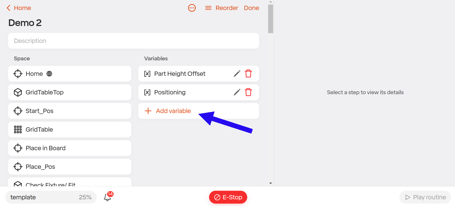
Step 2) Provide a name and an initial value for your variable.
Note: In this example we are making a part height offset and our initial value will be 1.
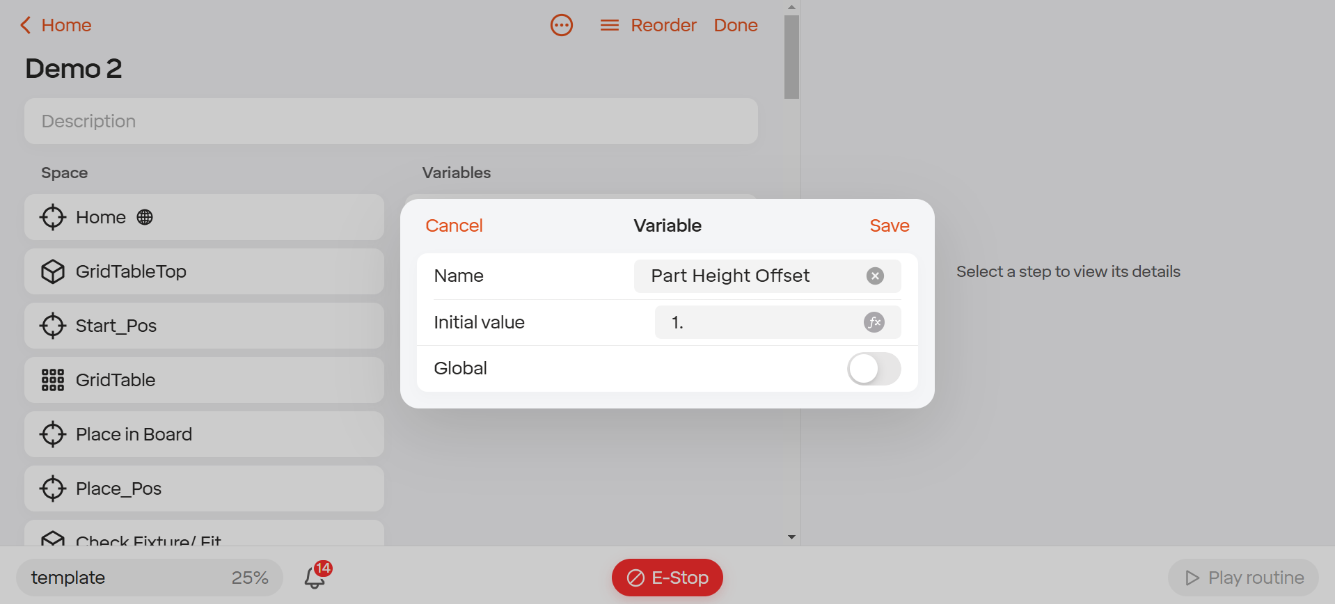
Step 3) To make this variable global click the switch that is labeled global. This should turn green. Click Save.
5.11 Exporting/Importing Routines
5.11.1 Introduction
This section provides a detailed guide on exporting and importing routines to and from your robot. These operations can be performed either through the Standard Bots App or by directly accessing the robot via its web address.
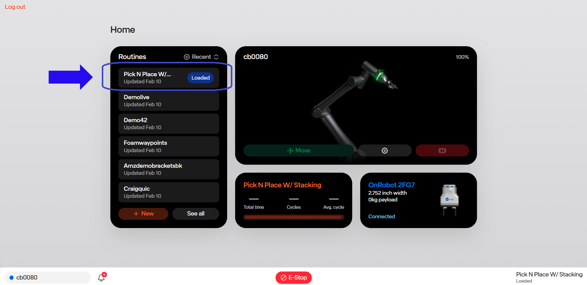
5.11.2 Exporting Routines
Step 1: Access the routine you wish to export. In this example, we will be exporting the routine titled “Pick N Place W/Stacking.”
Step 2: After opening the routine, locate the “Options” button at the top of the page. Click this button to reveal a drop-down menu.
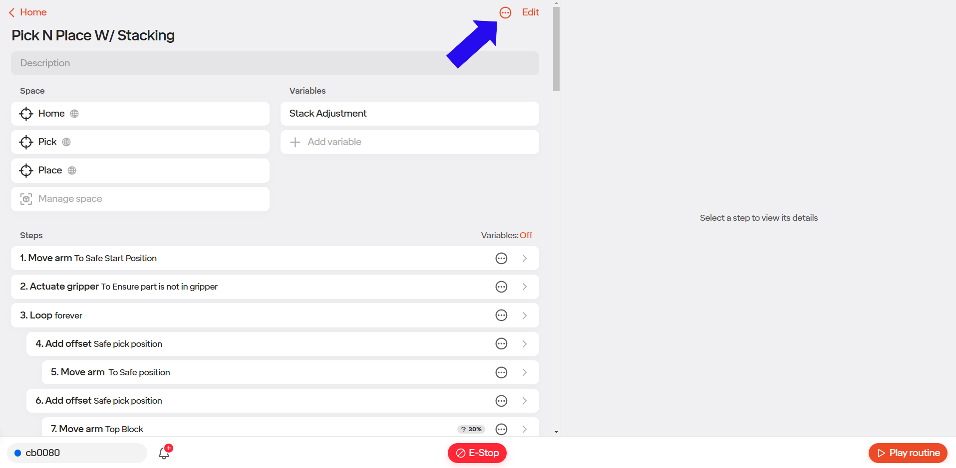
Step 3: From the drop-down menu, select “Schema.”
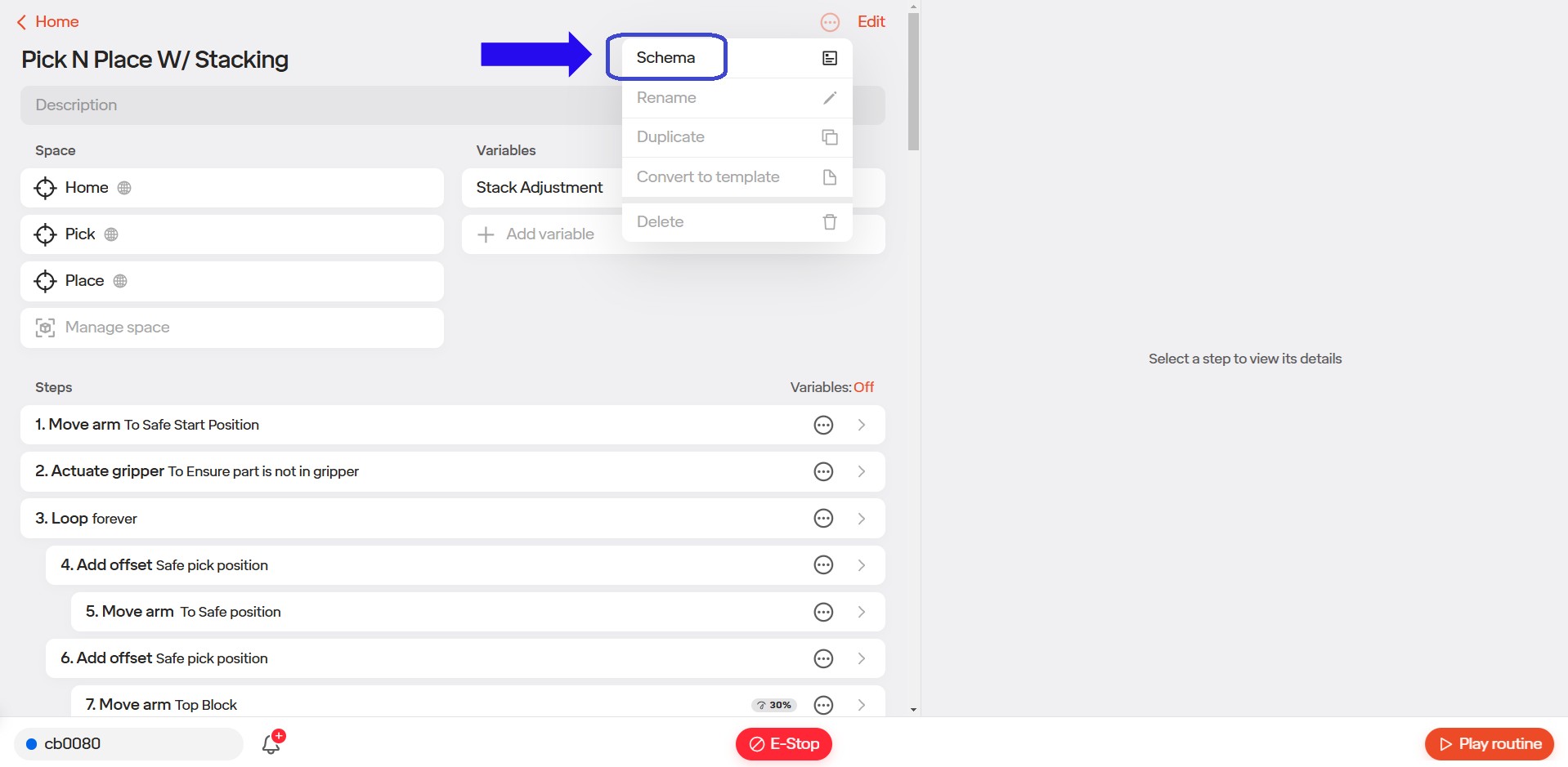
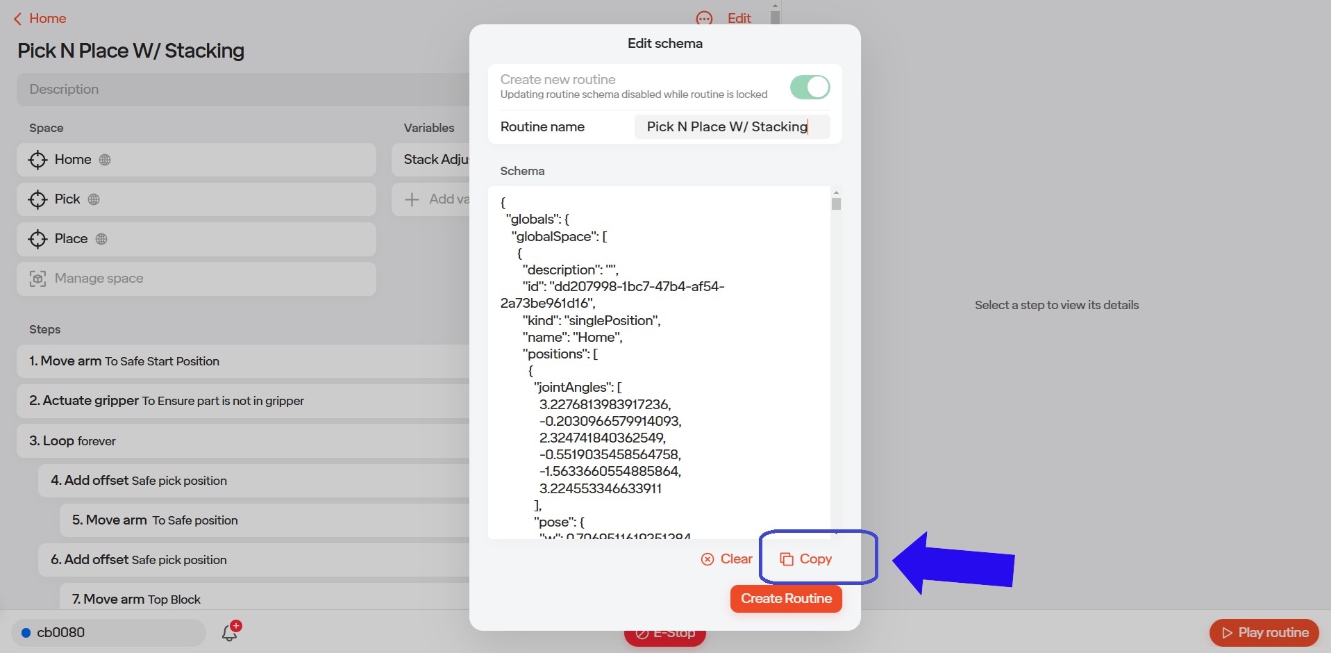
Step 4: Once the Schema is open, locate and select the “Copy” button. This will copy the Schema text file to your clipboard.
A confirmation message will appear in the lower-left corner of the screen once the selection is made.
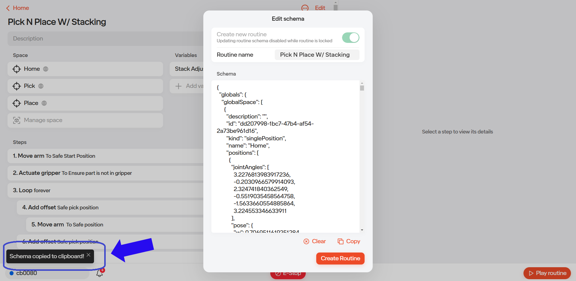
At this point, you can paste the text file into any word processing software, allowing you to save and store the file for future use.
5.11.3 Importing Routines
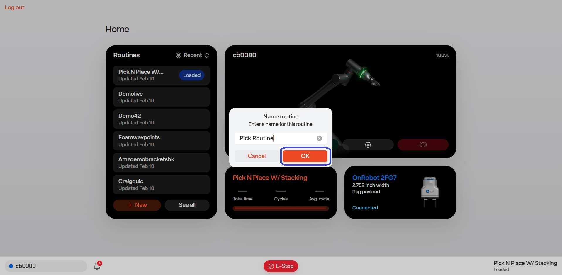
Step 1: From the main dashboard, click the “+ New” button.
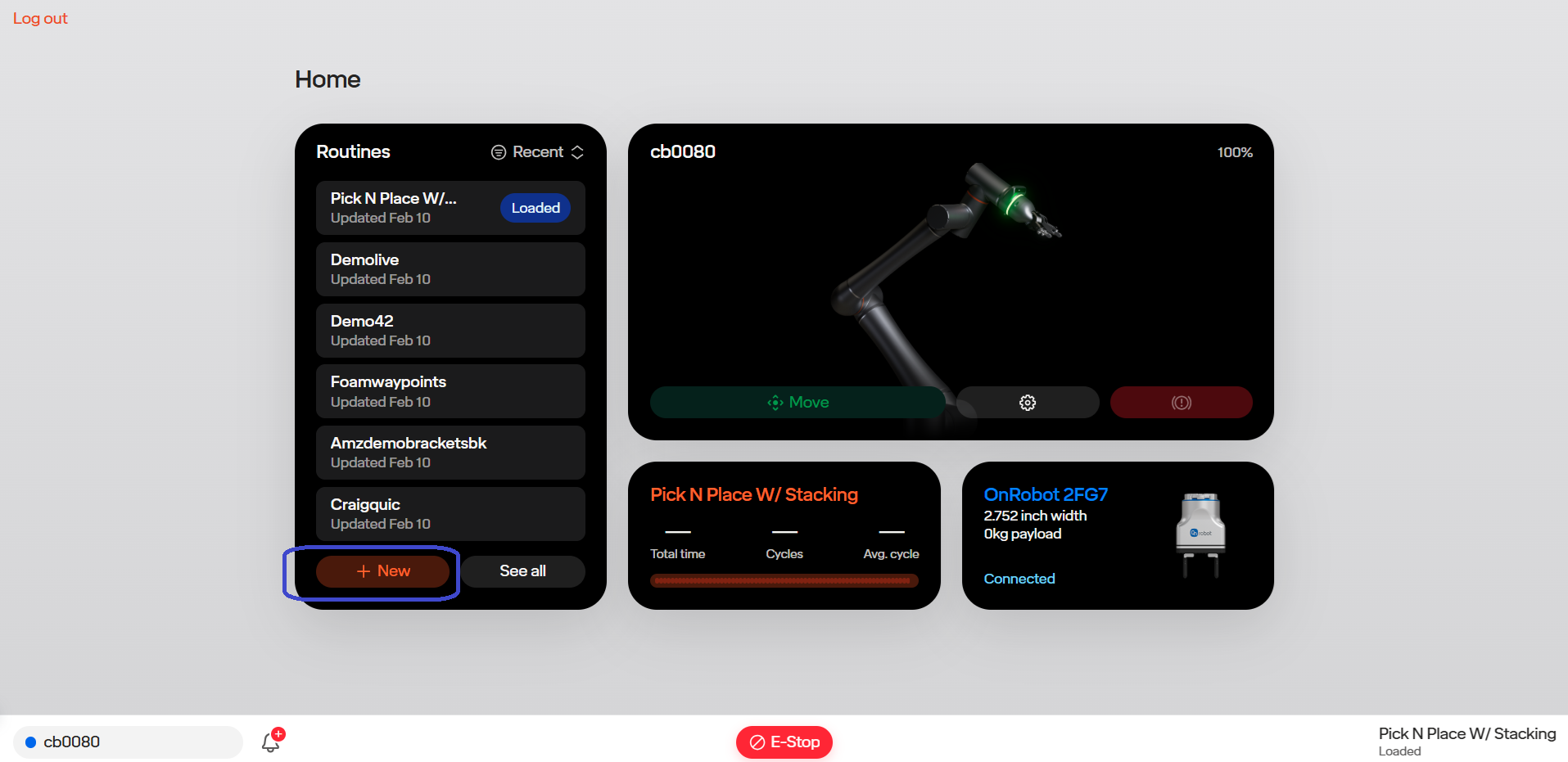
Step 2: Enter a name for your new routine and click “OK.” For this demonstration, we will name the routine “Pick Routine.”
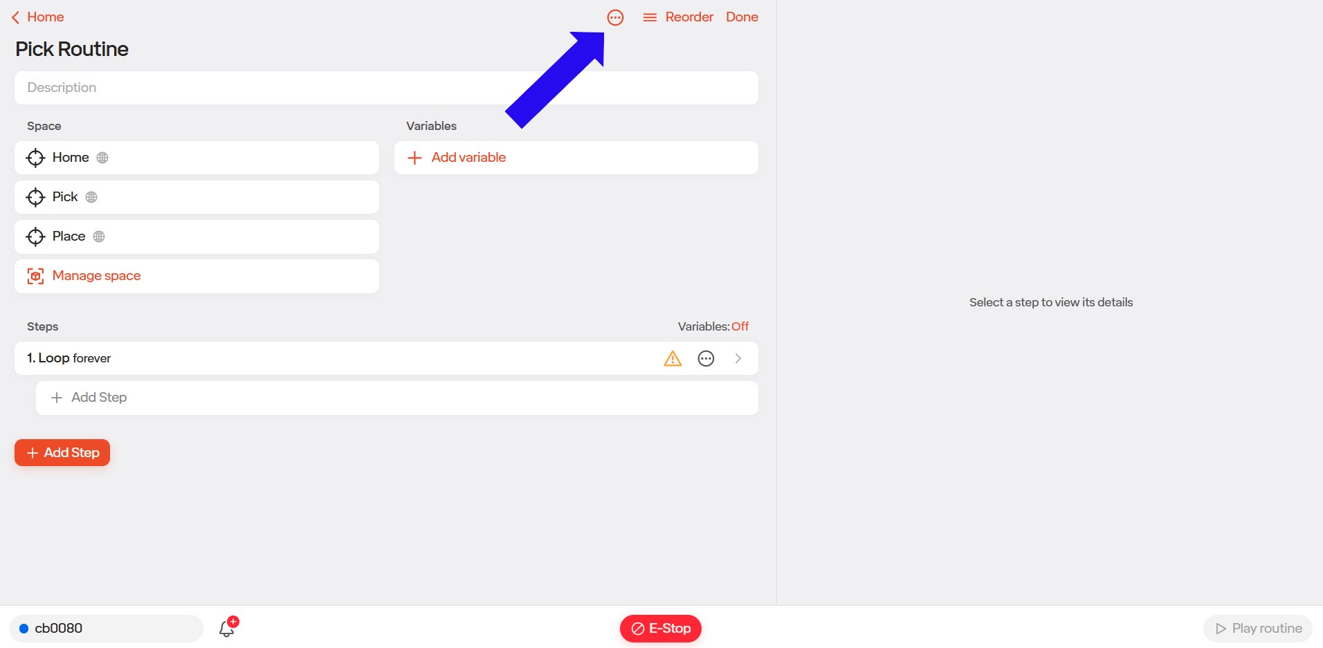
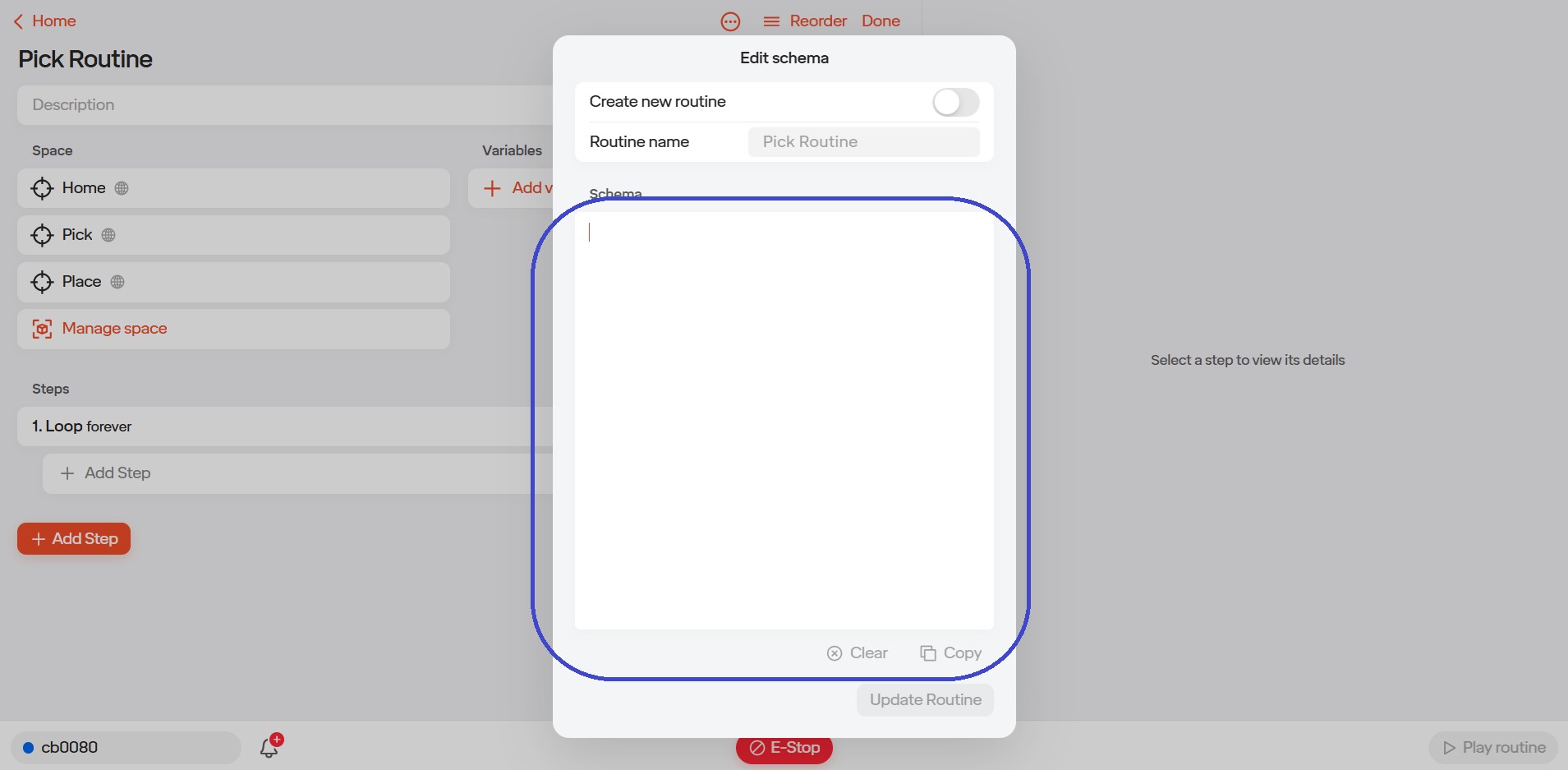
Step 3: With the new routine open, locate the “Options” button at the top of the page. Click this button to display a drop-down menu.
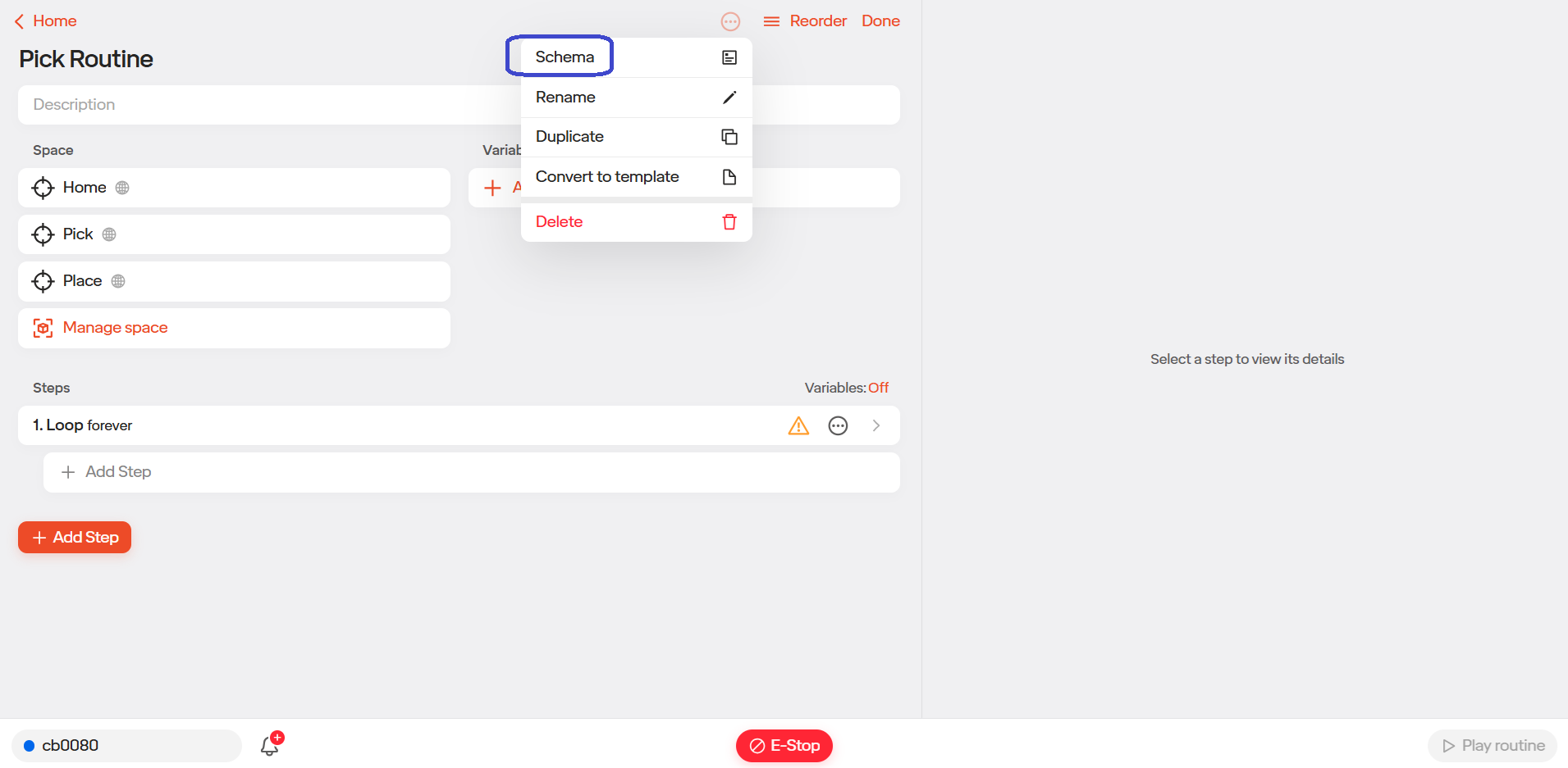
Step 4) From the drop-down menu, select “Schema.”
Step 5: When the Schema is open, locate the “Clear” button at the bottom of the popup and select it.
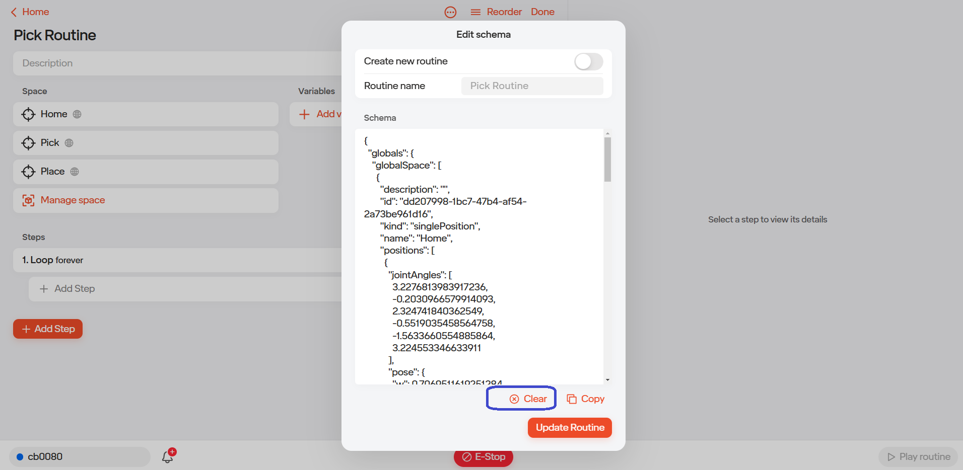
Step 6: After the Schema has been cleared, paste the desired routine into the Schema window and click “Update Routine.”
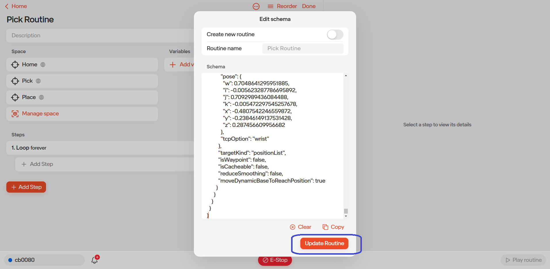
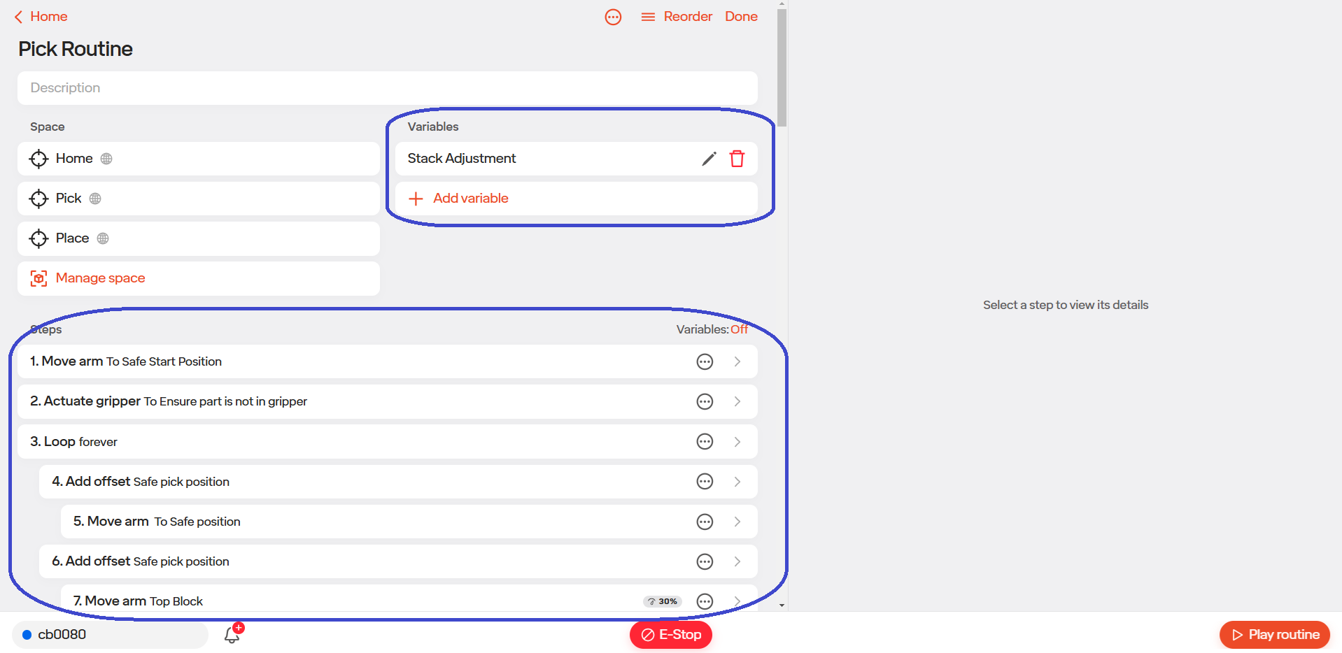
Step 7: After clicking “Create,” the routine will be updated, reflecting all spaces, variables, and steps from the imported schema. Note: In this example, global variables were used, which is why no visual change was observed.
5.12 Updating Your Routine to Use V2 Move Steps
In this section we will discuss how to upgrade/migrate existing routines to use the improved waypoint functionality. Note: This applies only to routines created prior to the release of the Waypoint Move feature V2. The Waypoint feature requires the feature flag to be enabled. If you need assistance activating it, or are unsure if it is already active please contact support at [email protected]
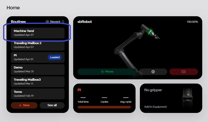
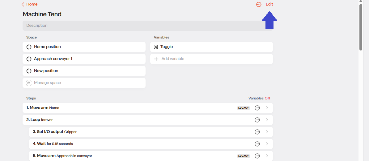
Step 1: Open the Routine Navigate to and open the routine you wish to upgrade. Example: For this guide, we will use the routine titled “Machine Tend”.
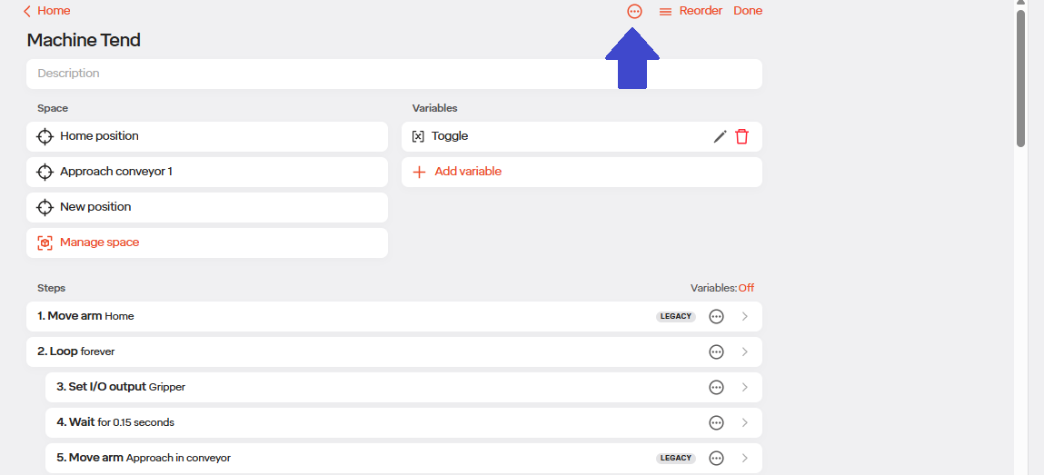
Step 2: Access Edit Options Click the “EDIT” button, then select the “Options” button located at the top center of the routine screen to open the dropdown menu.
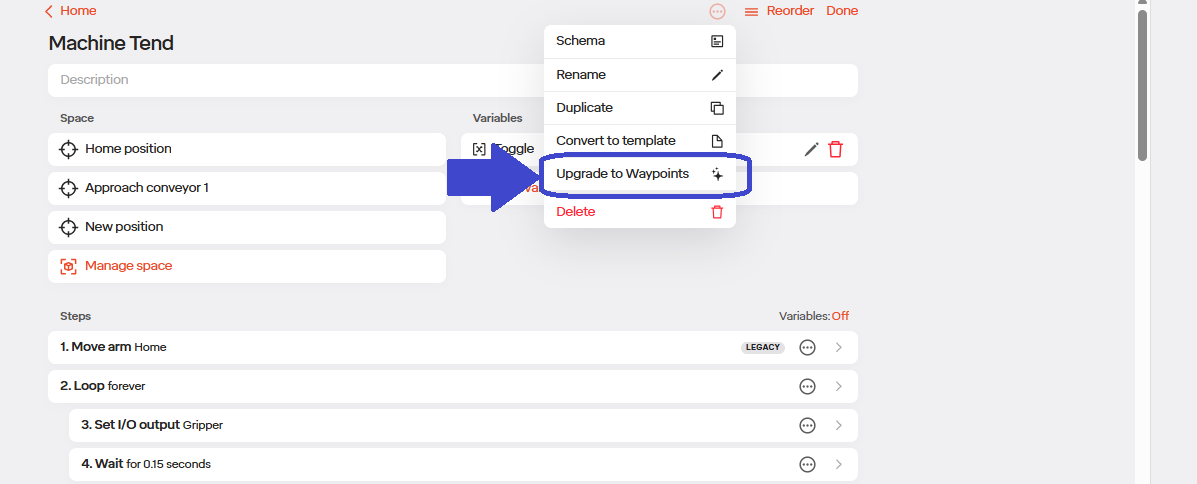
Step 3: Select Upgrade Option From the dropdown menu, choose “Upgrade to Waypoints”.
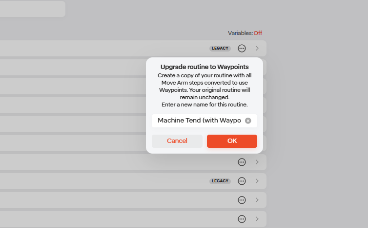
Step 4: Name the Upgraded Routine Enter a new name for the upgraded version of the routine.
Note: This process creates a duplicate of the original routine. The original will remain unchanged. Click “OK” to confirm.
Step 5: Locate the Upgraded Routine Return to the main dashboard. The newly upgraded routine will appear at the top of the routines list.
Note: If the original routine was created prior to the release of Waypoints V2, its steps may be labeled as “Legacy”. These labels will be removed automatically after the upgrade is completed.
5.13 Recovery Mode
To access the recovery mode through the user interface, follow the steps below: Navigate to the user interface. Within the routine click edit and select manage space. Tap the three dots menu located in the upper right corner. From the drop down menu, select recovery mode. Clict the start recovery to begin the process. Once the system has entered recovery mode, you will be able to modify the live payload, if required.
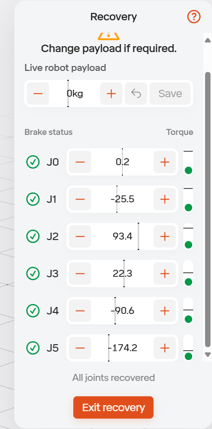
On the left side of the display is the brake status. Here there will be a green check mark once the robot is safely recovered. On the right side of the display is the torque bar. This is a quick visual indicator of how much load is on that joint. By using the “+” and “-” buttons beside J0, J1,J2, J3, J4, and J5 you will be able to recover your robot. These controls let you manually adjust joints to safely recover from a fault, collision, or unexpected stop. Once all joints are recovered, you can exit recovery and resume normal operation.
5.14 Offline Updates Overview
Step by step In the event of having to do an offline update we will send the file you will need upon request.
Step 1: Extract the (.tar) file from the download; then copy the extracted files to the root folder of a USB drive. - This might take some time because it is quite a large file. - This is different from the Production version (PRD), but it is acceptable for now.
Step 2: Insert the USB into the control box. (be sure that the control box is up to date with the main) - Wait until a blue dot appears.
Step 3: Install the update - On the iPad access the UI, go to menu, click “settings” then “software update”. - Then on the software update tab, click on “Install”, where the USB drive has been detected. - This will probably take around 25 min.
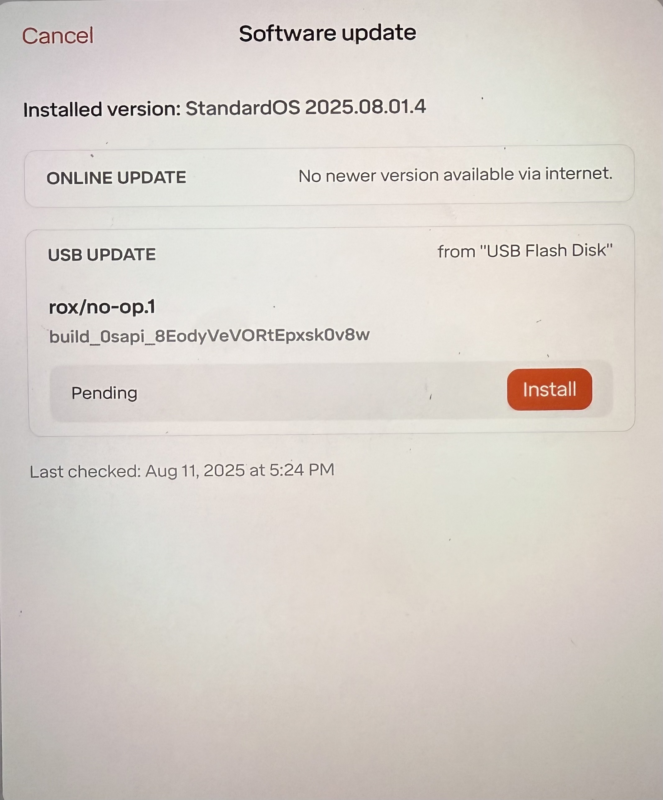
Step 4: Once the installation is complete, confirm the new version appears as the “current version”. - When the cb reconnects, it should automatically syn with the correct target build.
5.15 Using Run in Background steps in Routines
The Run in Background step lets you execute a group of non-motion actions in parallel while the main routine continues to the next steps. It’s ideal for things like timers, I/O handling, data logging, or condition monitoring that shouldn’t block robot movement.
How to use it (UI)
Step 1: Open the routine and click Edit.
Step 2: In the step list, place the cursor where the background work should begin.
Step 3: Click Add step then choose Run in Background.
Step 4: A new Run in Background block should appear. Click inside the block.
Step 5: Add the steps you want to run concurrently (e.g., Wait/Delay, Set/Read I/O, variable updates, loops/conditions). - Keep motion out of this block (No Move Arm step).
Step 6: (Optional) Rename the block to describe its purpose (e.g., “Monitor Clamp Sensors”).
Step 7: Add/continue steps after the block, these steps will run immediately while the background block is active.
Simple Examples: Run in
Background
- Repeat until part_detected = true - Read DI
Part_Sensor → if ON set part_detected =
true
- Wait 100 ms
Main routine
- Move Arm to Pick Position
- Wait Until part_detected = true - Close Gripper
- Continue…
5.16 Palletizing with pallet base and boxes
This section explains how to set up a pallet base along with the pallet boxes you will need for palletizing.
Step 1: Add a Pallet Base Open your routine and click Edit > Manage Space. Click the + icon in the upper-right corner next to Space. Select Pallet Base. Enter a name and description, then click Create. Then define the pallet dimensions: adjust the corner position(X, Y, Z values) also you need to set the pallet size manually or use a preset pallet size. Once finished, click Back to return to the main space menu.
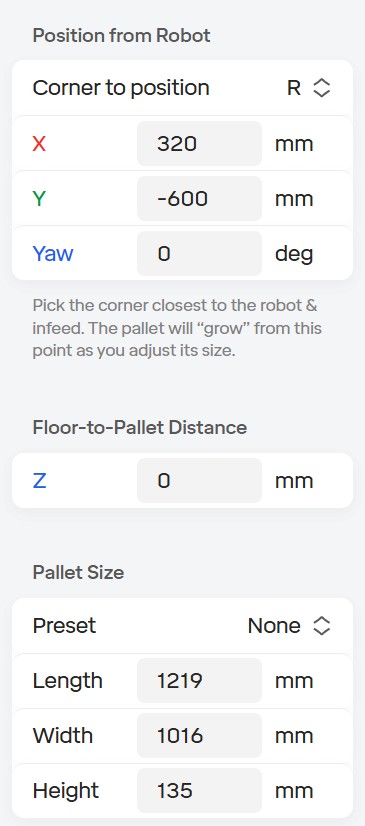
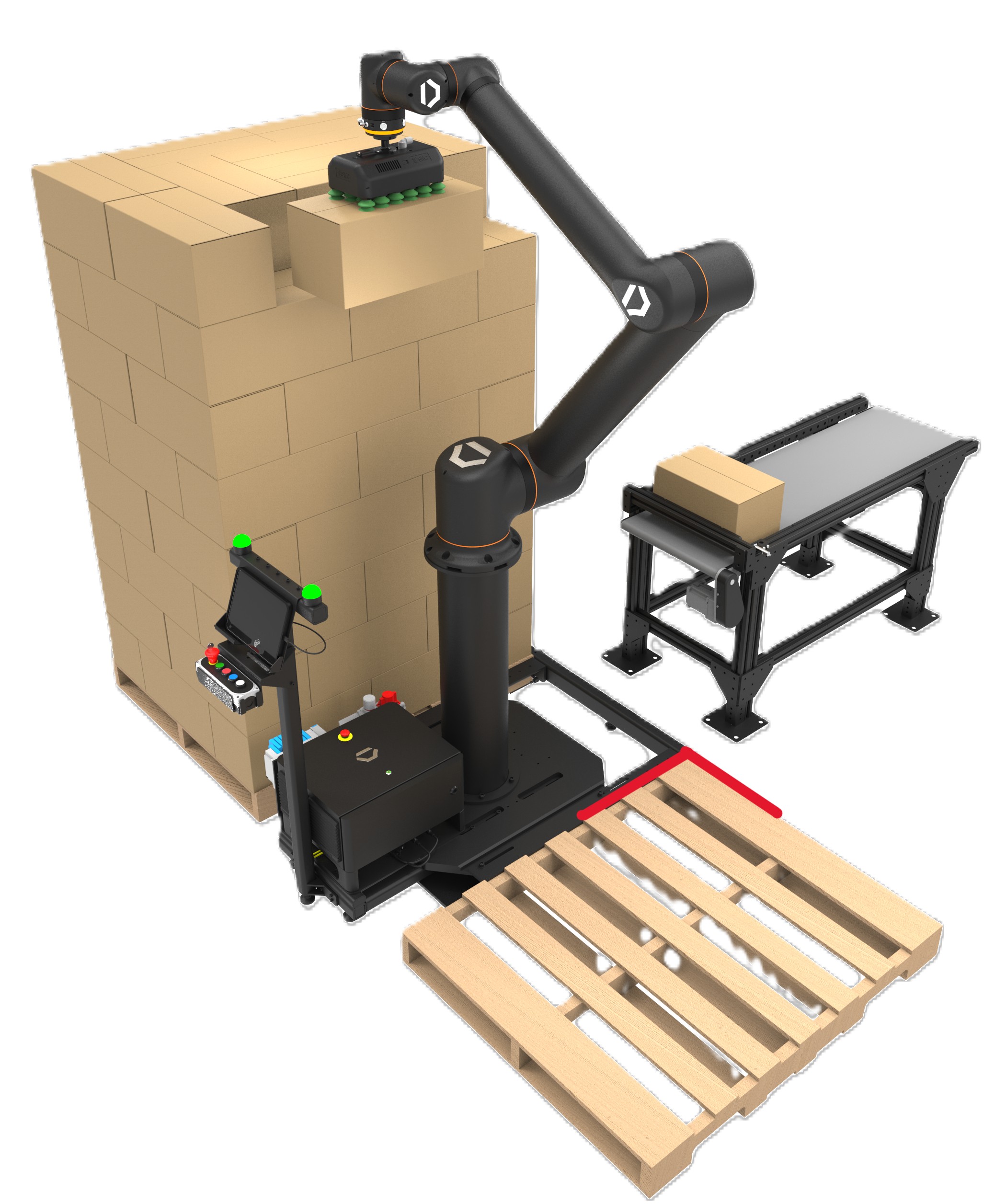
In the image below, highlighted in red around the corner shows the corner location of the pallet relative to the base of the robot
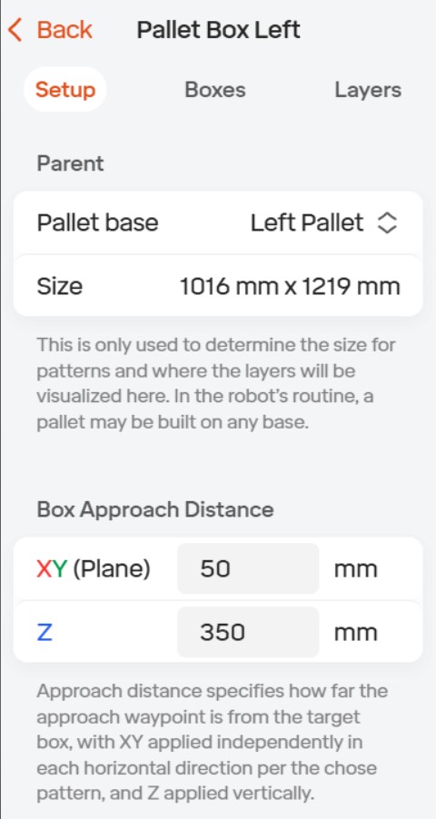
Step 2: Add Pallet Boxes From the Space menu, click the *+* iconand select *Pallet Boxes*. Enter a name and description, then click create. There are three different parts of this setup first you will need to onfigure the *set up*: First you will select the correct pallet and pallet size under the *parent* section. Then under the *Box approach distance* you will then set the approach distance which is how far the approach waypoints are from the target box.
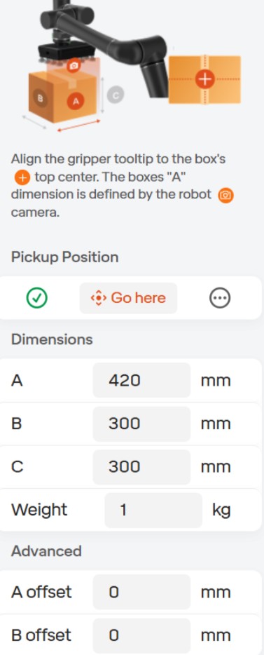
Define Box Properties Click the *Boxes* tab in the middle of the menu, then click the *+* icon in the upper-right corner. Here you will then need to define the dimensions, weight, and pickup positions for boxes (SKUs) that will be placed in the selected pallet. Before defining the dimensions be sure to have the robot in the pick position above the conveyor to be sure the box is in the right orientation. When defining the box Dimensions you need to remember that dimension *A* is the side of the box that will be parallel with the EOA camera while dimension *B* is the side of the box that will be perpendicular to the camera and dimension *C* will be the height of the box.

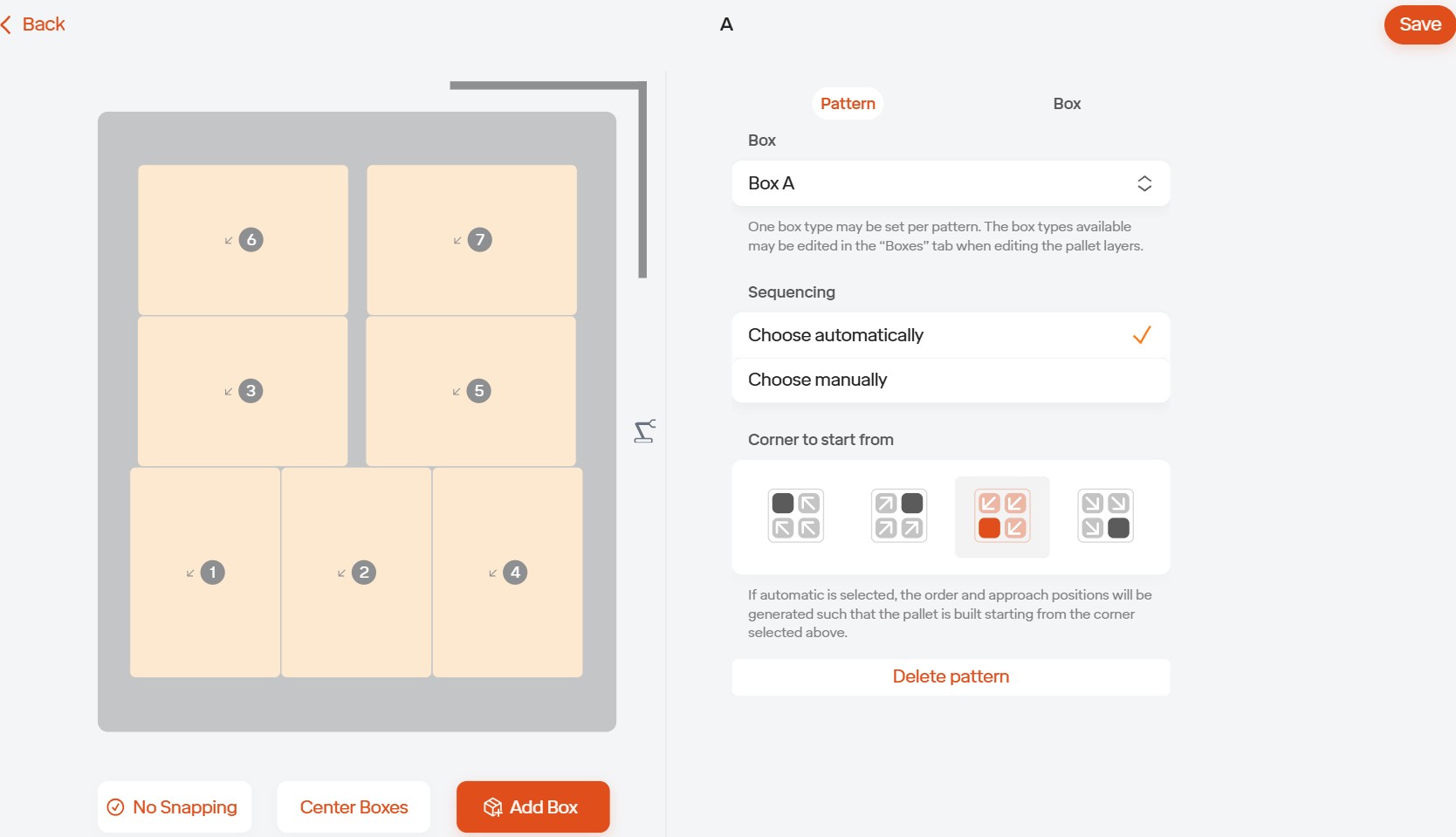
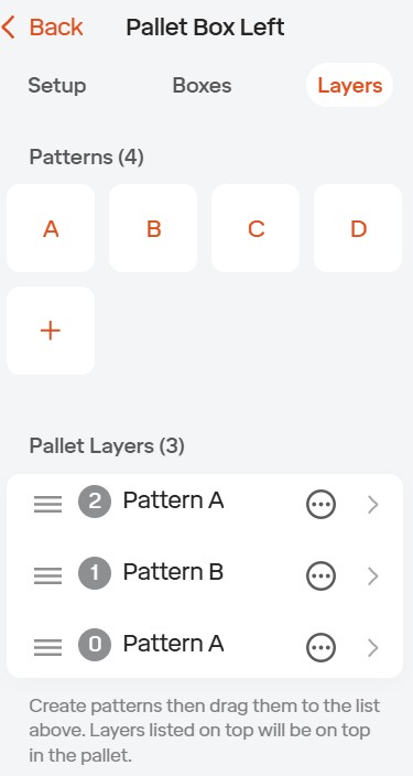
Create Box Layers Go to the *Layers* tab and click the *+* icon under patterns to create a new pattern. Once here you will first need to slect the correct box you will be using for this certain pattern. Then pick the sequencing in which to place the boxes automatically or manually along with selecting the corner in which to start from. Once this is done you can begin to click the *Add Boxes* button on the bottom left side of this window, you can also use the *No Snapping* button to freely move the boxes, if not they will automatically be placed next to each other at whatever distance that you have set.
Finalize the Layout In the *Layers* tab, drag and drop each *pattern* into the *pallet layout* in the order of which the boxes will be placed on the pallet. Once all layers are placed, your pallet base and boxes are fully configured and ready to go.
Once this is finished you should move the robot to each box position to be sure the robot can reach and so the software can validate that the robot will be able to reach each position correctly.