3 Assembly & Setup
3.1 Requirements
The RO1 has the following utilities requirements:
| Utility | Requirement |
|---|---|
| Electrical | 90 ~ 264VAC, 47-63Hz, 15 A maximum at 120VAC. |
| Internet | Wi-Fi or RJ45 (Ethernet) wired connection for remote updates and support. |
| Floor | 200 PSI capacity rating. Depending on application a floor capable of supporting lagging may be required. |
3.2 Lifting the RO1
Proper lifting techniques should be observed when lifting the RO1 robot or controller. Improper lifting can cause strains, sprains, and other serious injuries to the back, neck, shoulders, and other parts of the body.
To lift properly, start by standing close to the object with your feet shoulder-width apart. Bend at the knees and keep your back straight as you lift with your legs, not your back. Hold the object close to your body and avoid twisting your body while lifting or carrying the object. If the object is too heavy, ask for help or use equipment such as a dolly or forklift.
Remember to always warm up before lifting and take breaks when necessary to avoid fatigue. It’s also important to wear appropriate clothing and footwear that provides adequate support.
By following these guidelines and using proper lifting techniques, you can reduce your risk of injury and stay safe while handling heavy objects.
3.3 Setting Up the Base
Follow the steps below to set up the base for your Standard Bots robot.
3.3.1 Required Tools
4mm hex
6mm hex
10mm hex
3.3.2 Assembly Procedure
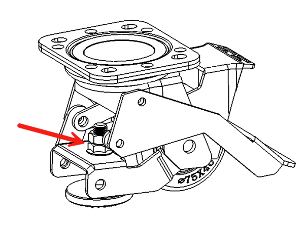
Lock the casters of the base (SBPN 428-00020-E) by stepping down on the caster lock levers.
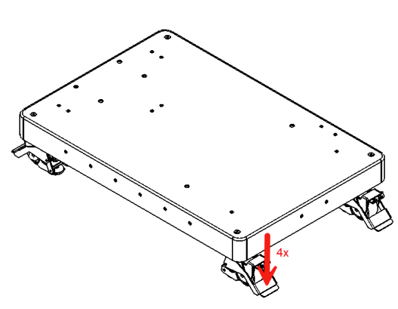
The caster feet can be adjusted to level the base. Make sure all 4 feet contact the ground.
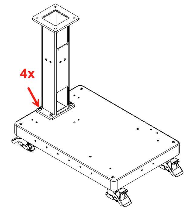
Mount the robot pedestal (SBPN 428-00021-D) where shown using 4x M12 x 1.75, 25 mm Hex Socket Head Screws (SBPN 465-02059-A). Tighten to 55Nm. Confirm the orientation of the pedestal matches the image below.
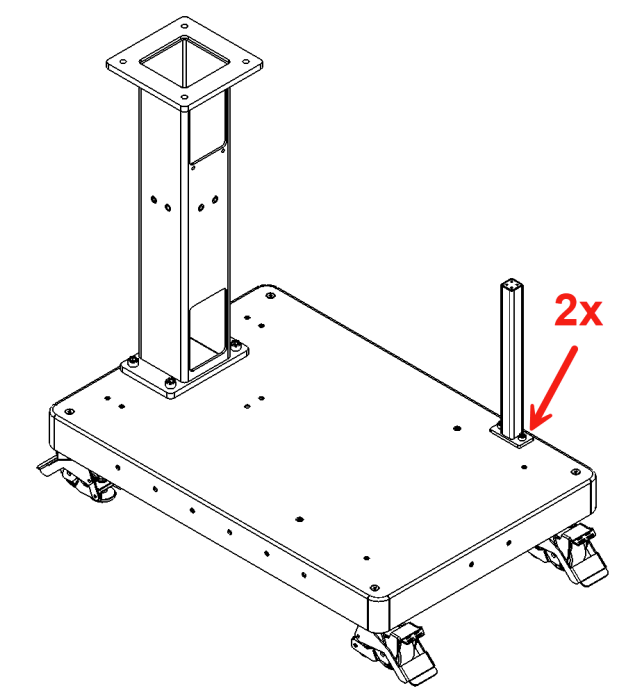
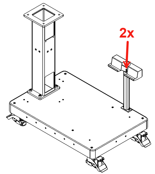
Mount the tablet pedestal (SBPN 408-00023-D) where shown with 2x M8 x 1.25, 20 mm, Hex Socket Head Screws (SBPN 465-01555-A). Tighten to 6Nm.
Mount the Tablet Pedestal Bracket (SBPN 402-00037-C) where shown with 2x M5 x 0.8, 20 mm, Hex Socket Head Screws (SBPN 465-01177-A). The Tablet Bracket can be rotated to mount in 4x directions, choose whichever orientation is most convenient for your application. Tighten to 4 Nm.
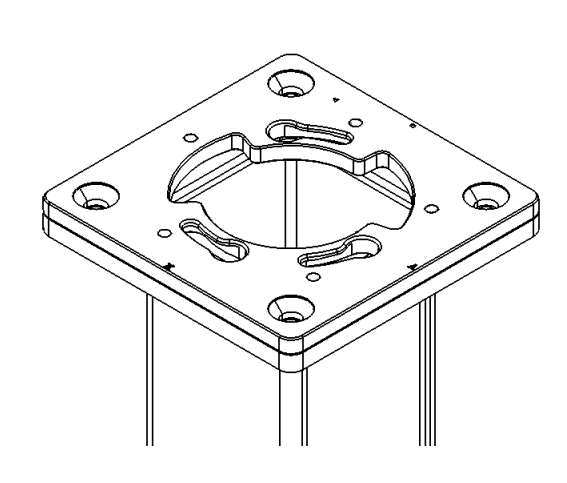
Install the Arm Mount Plate (SBPN SB-0192-F) on the Pedestal with 4x M14 x 2.0 x 30 mm Hex Flat Head Screws (SBPN 410-00049-A). Tighten to 55 Nm. The Arm Mount Plate can be oriented in 4x directions to position the Robot. For help, consult Standard Bots Application Engineering to determine the best orientation for your application.
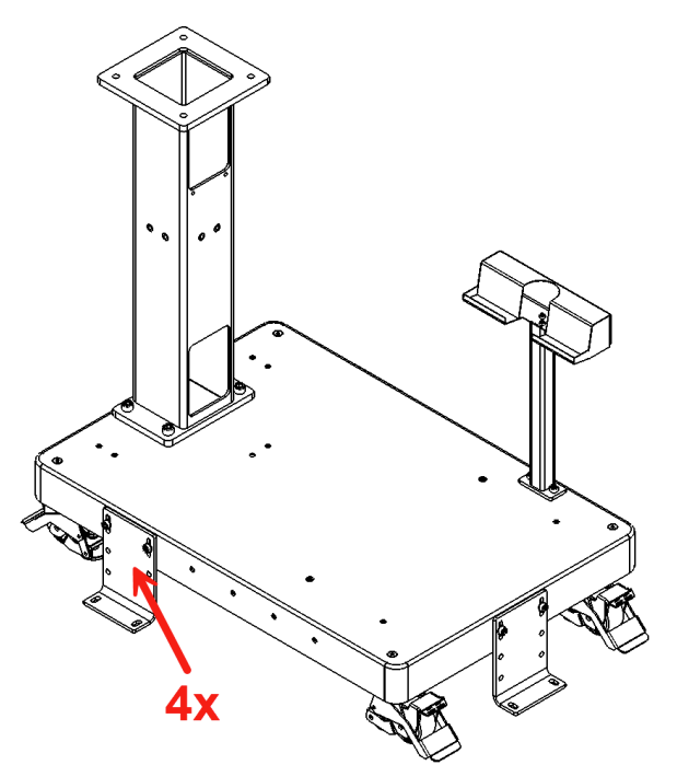
Optional: Install the Floor Brackets as needed. For large payloads and work envelopes, it is recommended to install 4x Floor Brackets approximately as shown. Use floor anchors to fix the brackets to the floor. Consult Standard Bots Application Engineering for details about your applications.
3.4 Connecting Control Box, Mounting and Unmounting Arm
3.4.1 Orientation
The RO1 only attaches to the base in one orientation. The orientation is shown by the X and Y markings on the baseplate, which line up with the tooltip orientation in the Move Robot view as shown:
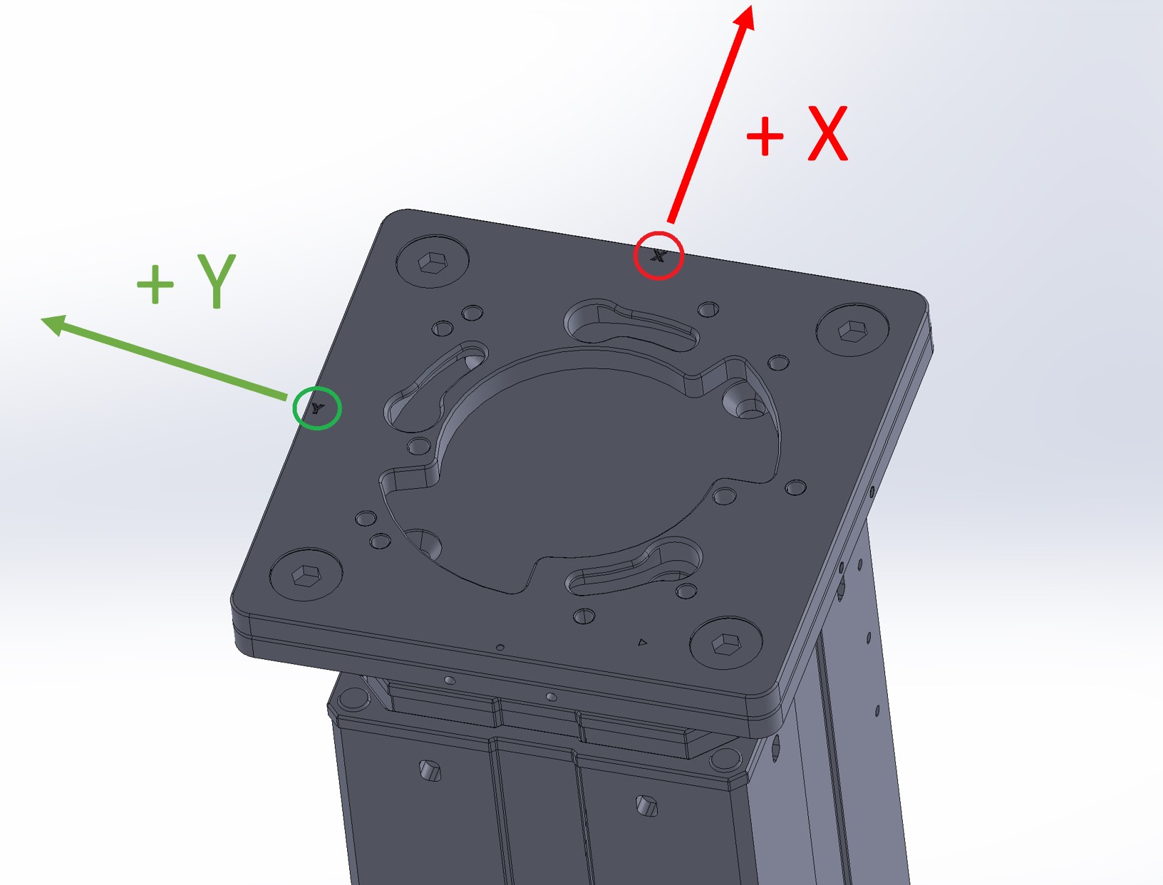
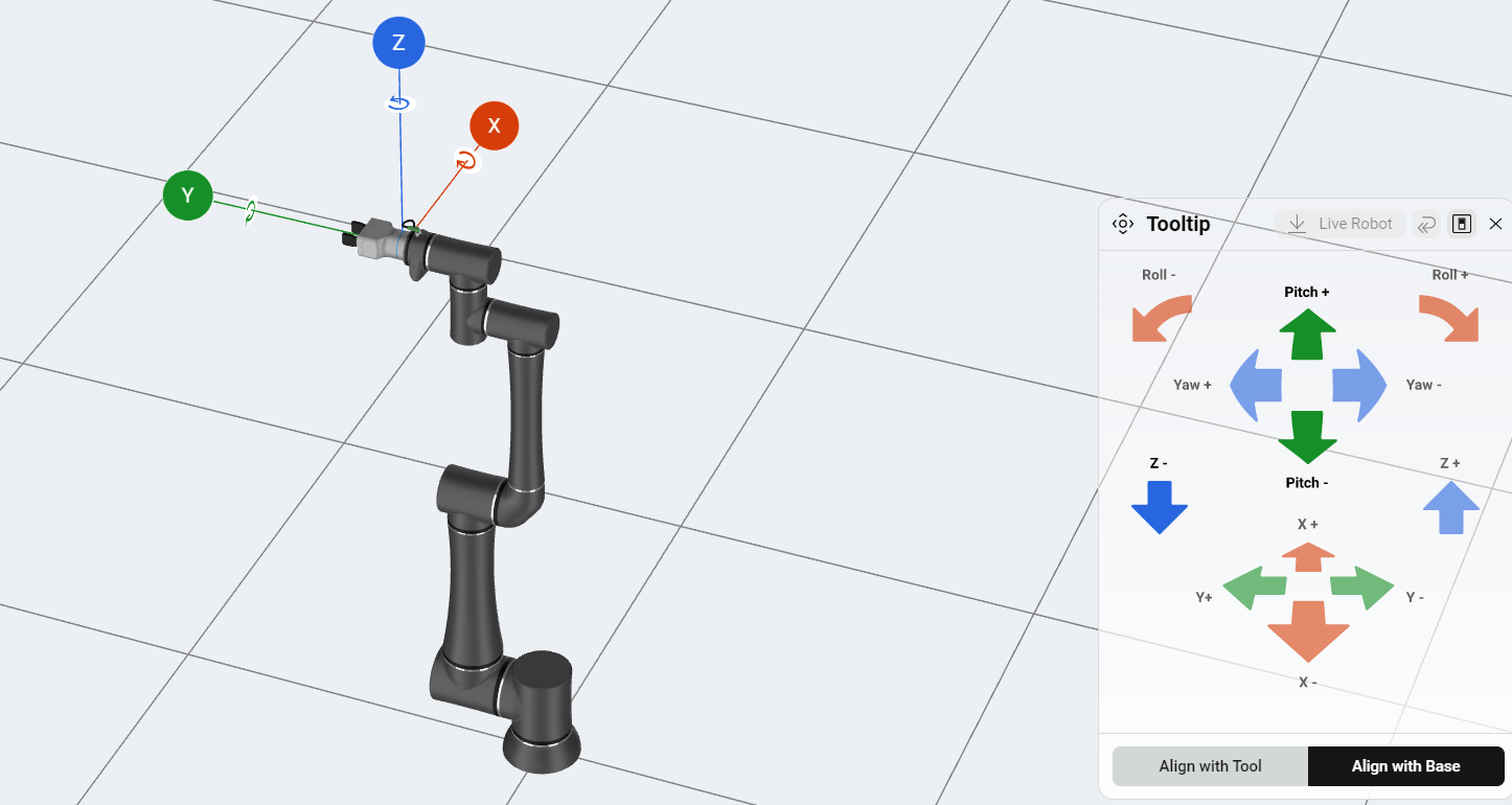
It is possible to rotate the robot in 90 degree increments by rotating the base plate.
3.4.2 Video
3.4.3 Steps
To connect the control box and mount the arm on the base:
First, ensure the leveling feet have been raised on the base.
Lift the control box (with feet attached)
Hook the control box onto the base bracket.
Carefully lift the RO1 onto the base.
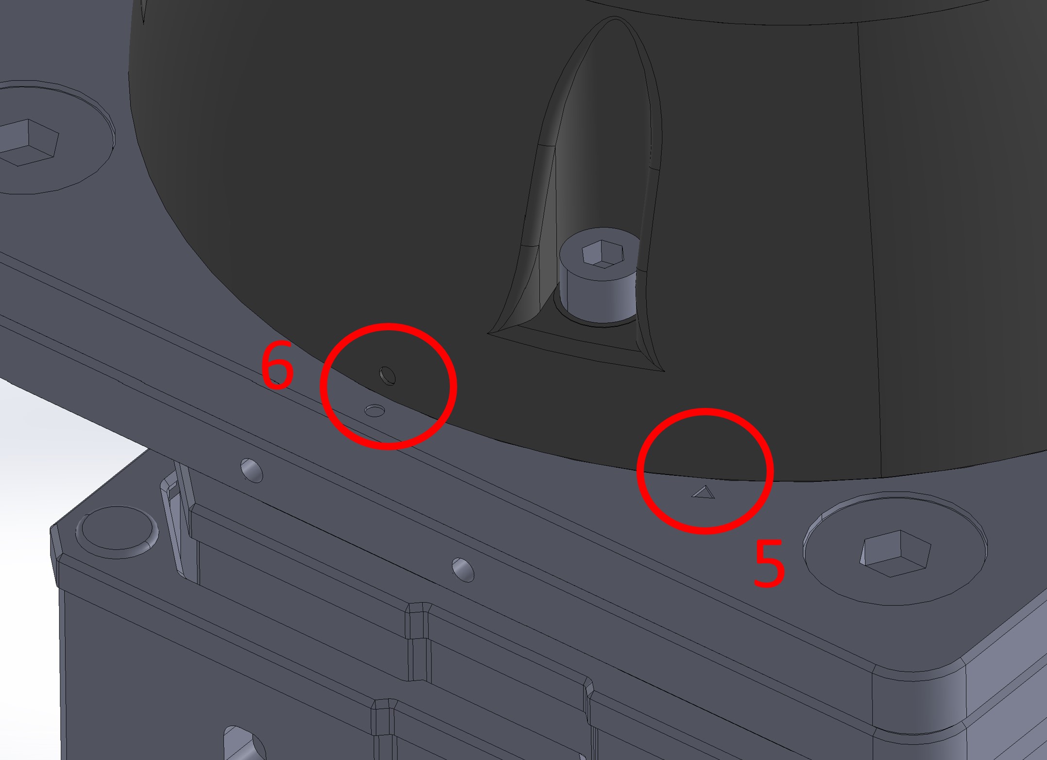
Place onto the pillar with the “O” on the robot base lined up with the triangle indicator shown above.
Rotate it clockwise until the “O” on the robot base lines up with the matching “O” indicator shown above.
Secure the RO1 base joint using five M8 30mm screws.
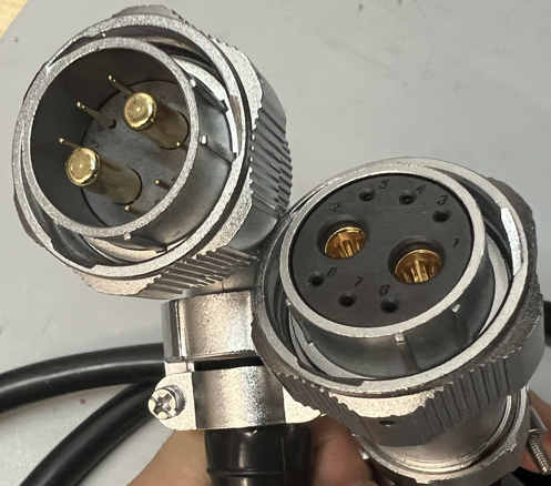
Connect the RO1 USB-C cable to the base joint. Connect the RO1 power and data cables to the base joint.
Note: there is a different style power cable used than what is shown in the video for newer made control boxes and robot arms. Same steps apply.
Use cable ties to restrain the cables to the pillar.
At the bottom of the control box, connect the RO1 power and data cables to the control box, as well as the USB cable. Connect the IEC (power) cable and lock it with the clip.
Turn on the power switch that is located behind the door on the lower left corner.
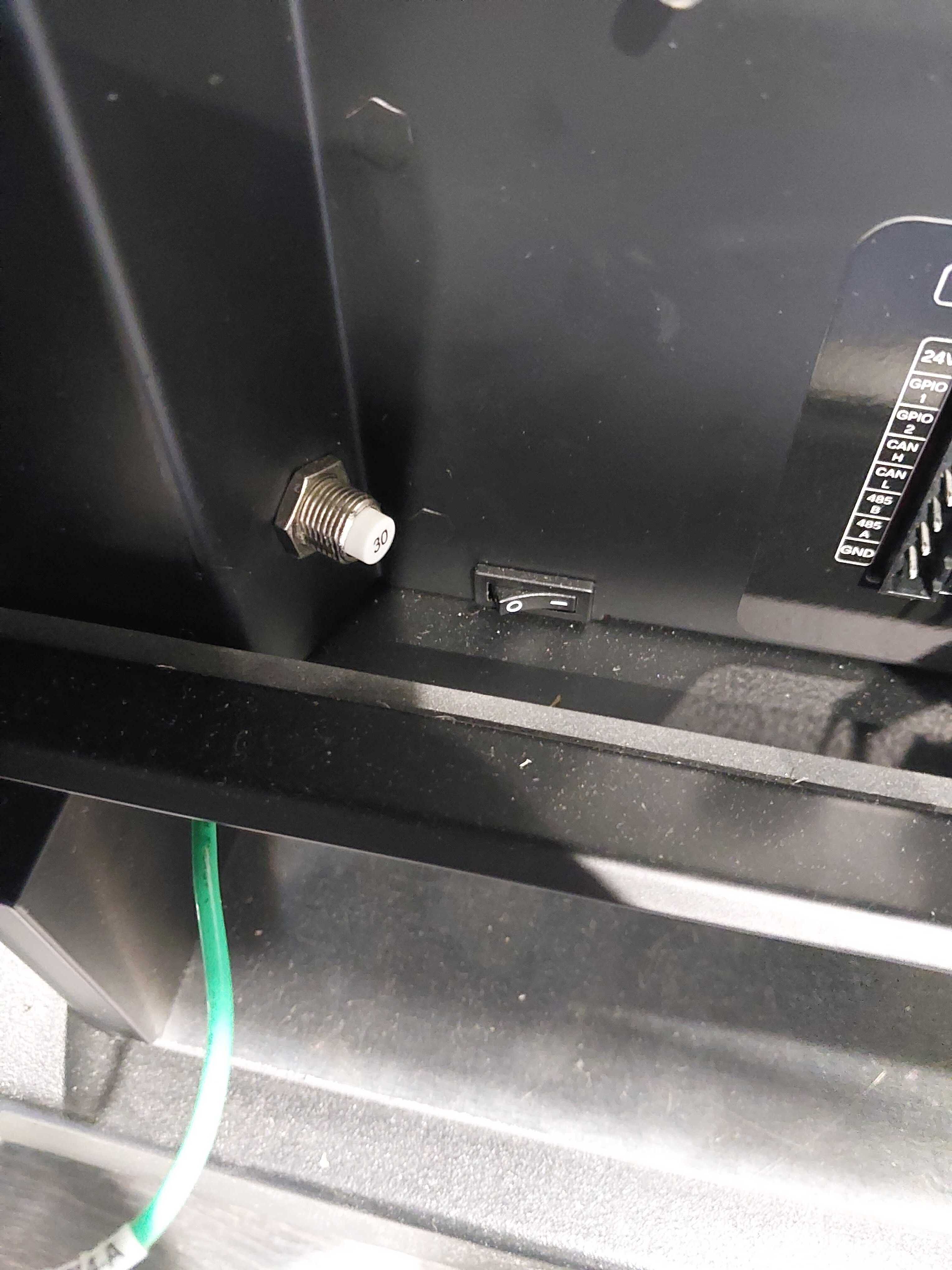
Press the power button on the top of the control box to start the RO1.
3.4.4 Mounting Base Diagram:
3.5 Setting up Tablet
The included iPad is used to configure, control, and program the RO1. Here’s how to get it set up: 1. Take the iPad out of the box and turn it on.
If prompted at any point, enter the default passcode of “0000”.
Open the “Settings” app on the iPad, then configure your network. If you are using Wi-Fi, there is a “Wi-Fi” section. If you are using an Ethernet adapter, an additional option to configure Ethernet should appear in the right sidebar.
- When connecting your robot to Wi-Fi, please make sure that it does not require to go through a splash-page to access.
Navigate to the home screen (by pressing the bottom button, if the iPad has one, or swiping up from the bottom, if it doesn’t). Open the Standard Bots app.
Open the Standard Bots app.

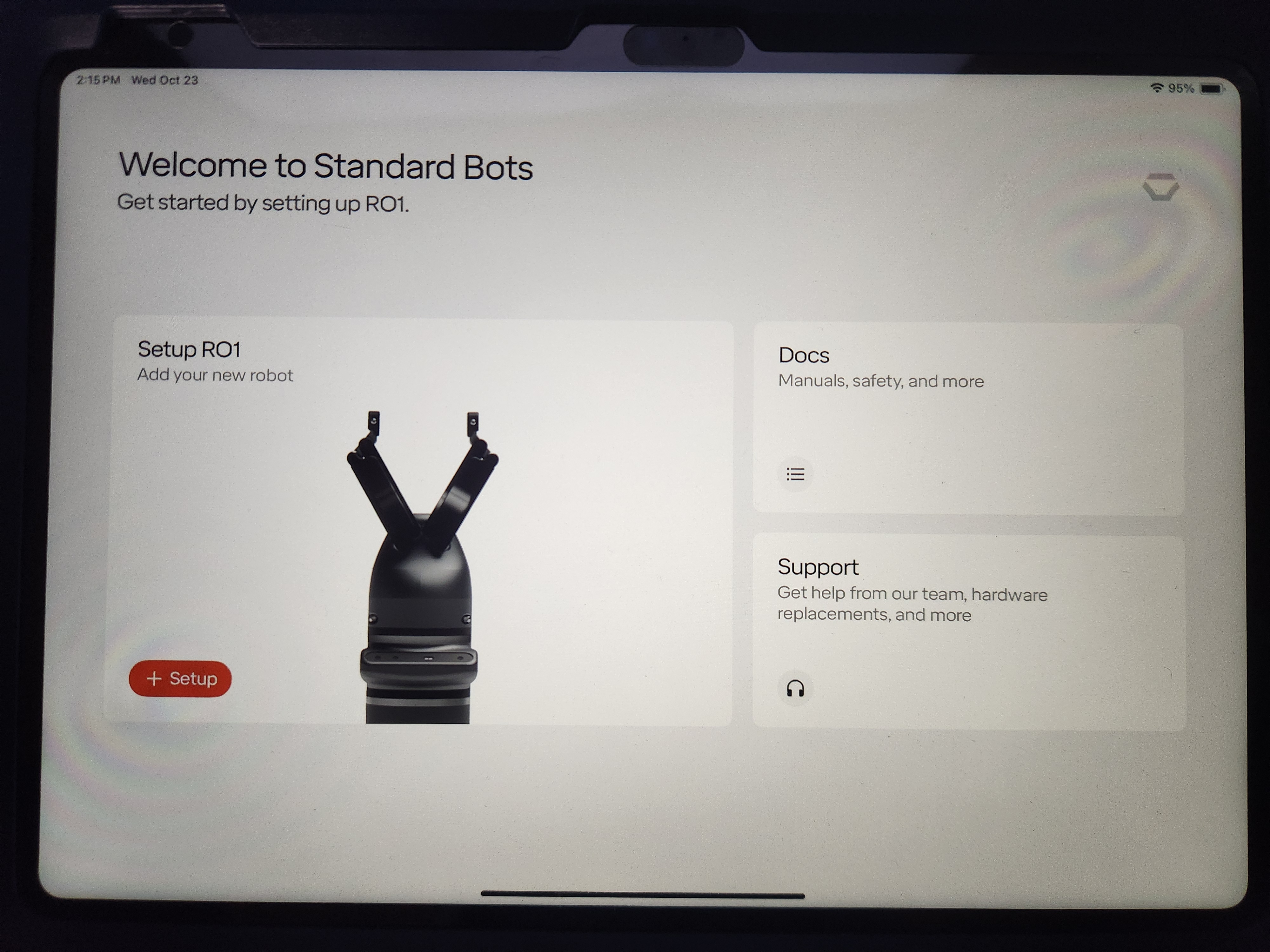
You will be brought to the home screen of the Standard Bots app. Here you will see three blocks. The top right named Docs will bring you to the Standard Bots manual. The bottom right block, named Support, will bring you to a tab that shows how to reach Standard Bots support line. It shows the support email, the support phone number, as well as the address of Standard Bots office. The large block on the left is where you will go to add your new robot.
Tap “+Setup” on the home screen.
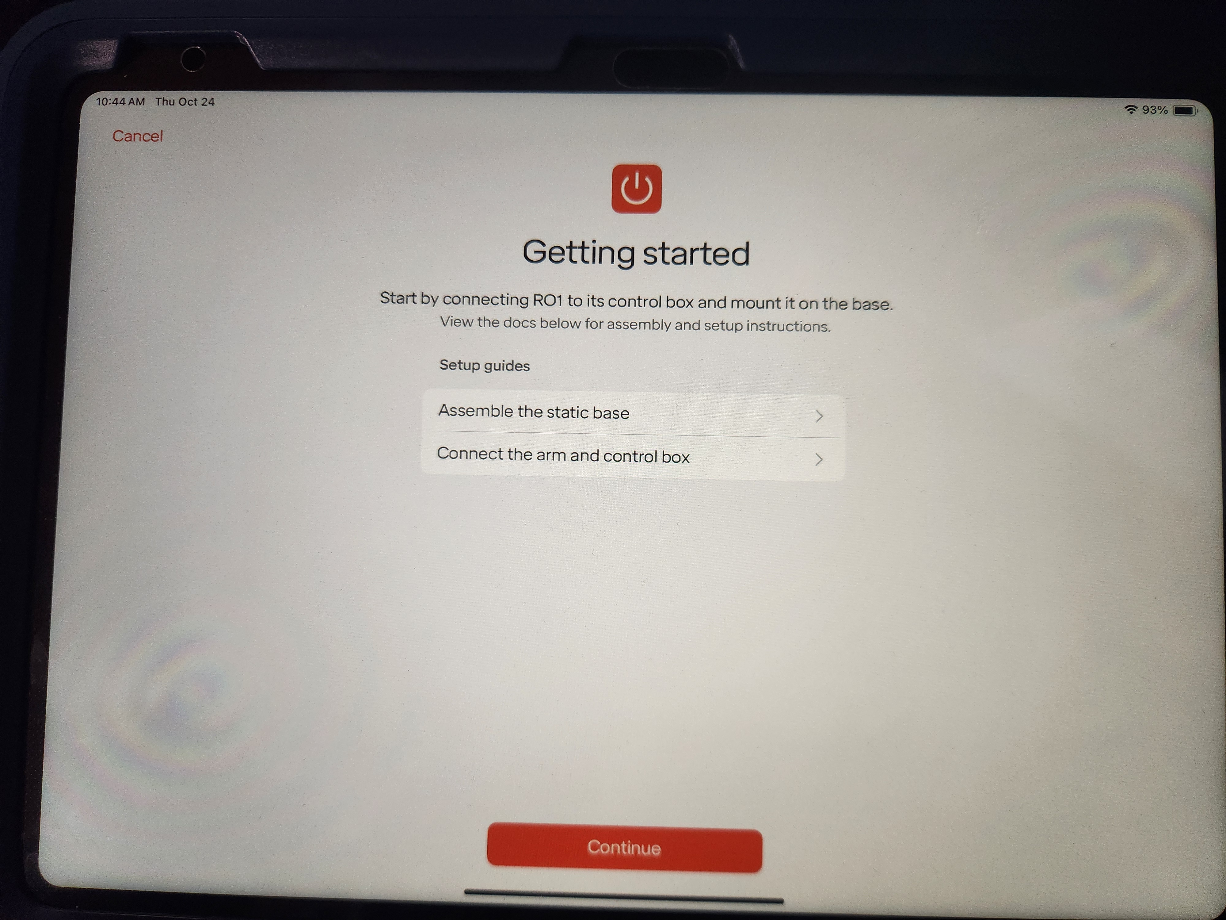
You will be brought to the Getting Started page. Here you can also find guides for how to assemble the robot base as well as how to establish connection between the robot arm and the control box. Once ready, press the Continue button
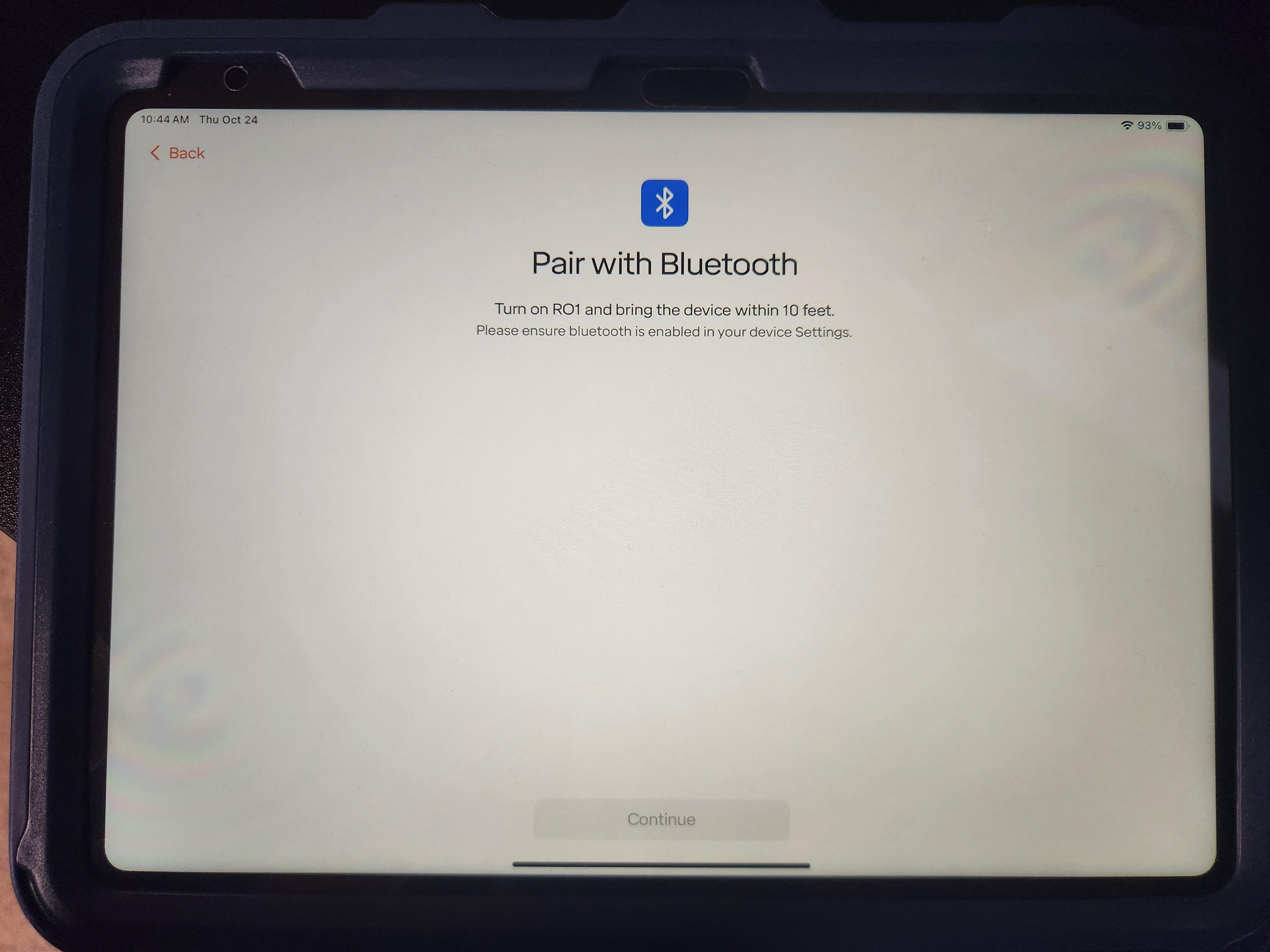
The Pair with Bluetooth page will appear where the iPad will search for the robot over Bluetooth. Make sure the RO1 is turned on and has the included antennae screwed on. Once the RO1 shows up, choose it from the list and proceed.
The app will ask you to enter your network credentials again. You can configure the robot to connect over Wi-Fi or Ethernet, regardless of how your tablet is connected.
The app will also walk you through setting a PIN and choosing a name for your RO1.
After setup is completed, you can connect to your bot.
Once connect you can reset the estop (if required), unbrake, and begin jogging the robot. Refer to Section 5 for more details on operating the robot and constructing routines.
3.6 Unmounting & Transporting
3.6.1 Warnings
- Do not attempt to move the arm while it has power unless you are
utilizing the any-gravity mode.
- Do not force the robot into a position while power is off, doing so may damage the robot.
- Only lift the RO1 arm with 2 people.
- The RO1 robot has a locking feature in the base of the robot. Do not attempt to force the robot straight off of the mounting structure.
3.6.2 Before transportation:
- Ensure the robot is in the desired position for
transportation.
- If needed, the robot can be put into the position required for the
original box by:
- Navigating to the Move Robot view
- Go to the Robot menu in the upper right
- Select “Settings”
- Select “Box Robot”
- Set the Payload
- Save and confirm the Payload
- Click and hold down the “Move Live Arm To Visualizer Position” button. The robot will move into the packing pose.
- Click the hexagon button in the bottom right of the Move Robot view
- Select “Brake Robot”
- Unplug the control box from the AC power source
- Wait 30 seconds for stored power to dissipate
- Unplug the connector between the arm and robot buy twisting the locking mechanism and pulling down on each end
- Disconnect any inputs and outputs from the control box
The RO1 control box has an integrated handle for ease of transportation. Ensure all cables are disconnected from the RO1 control box before moving or shipping the control box. Ensure RO1 control box is well packaged, preferable in the original packaging, before shipping the RO1 control box.
3.6.3 Unmounting the Arm From Base
- Ensure the robot is powered off, unplugged and in the desired position before removing, if needed follow the above instructions to get the robot in the proper position.
- Have 1 person steady the robot while the other removes the bolts.
- Use a 4mm Allen key, remove the 5 M8 top down bolts around the robot base.
- Ensure the robot is support, then have both people lightly twist the robot counter clockwise.
- The robot will unlock from the base
3.7 Connecting End Effectors
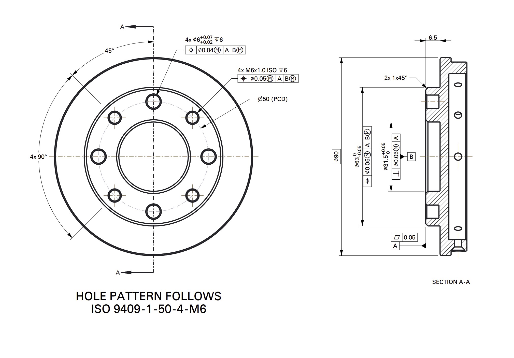
3.7.1 Mechanical Connection
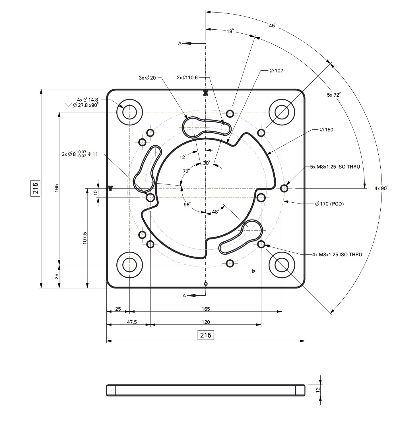
The RO1 robot uses a modified version of the standard ISO 9409-1-50-4-M6 50 mm ISO robot flange pattern. The RO1 offers four locations for the locating pin, where the ISO 9409-1-50-4-M6 standard offers 1 pin location. Any tool that follows the standard 50mm pattern will mount to the RO1 robot flange. A diagram of the mounting pattern is shown below.
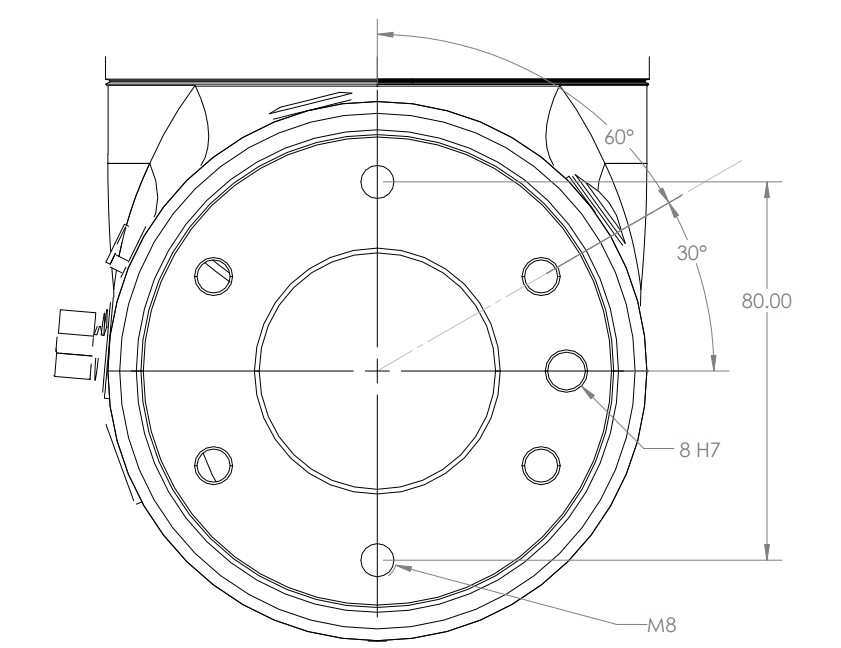
The Thor robot uses a modified version of the standard ISO 9409-1-80-6-M8 80 mm ISO robot flange pattern. The flange connector offers four locations for the locating pin, where the ISO 9409-1-80-6-M8 standard offers 1 pin location. Any tool that follows the standard 80mm pattern will mount to the Thor robot flange. A diagram of the mounting pattern is shown below.
3.7.2 Fully Integrated Tools
Standard Bots supports full integration with the following tools. These tools can be fully controlled using standard instructions in the Standard Bots Routine Editor.
- OnRobot 2FG7
- OnRobot 3FG15
- OnRobot Screwdriver
- OnRobot Dual Quick Changer
- OnRobot VGP20
Follow the instructions provided with the tooling to connect the tooling to the robot flange, and connect the wire to the provided connector at the end of the robot arm.
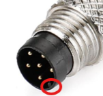
Be careful when attaching the m8 tool connector. Ensure that you line up the key with the receiver when you plug it in. Do not twist it, the pins are fragile and this can cause the pins to break.
3.7.3 Other Supported Tools
In addition to the above tools, Standard Bots generally supports most tools that mount to the 50 mm flange and that support 24VDC discrete control. Please contact Standard Bots support for assistance with confirming tooling compatibility.
3.8 Control Box Inputs and Outputs
3.8.1 Digital Inputs and Outputs
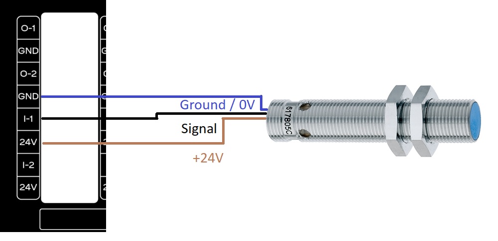
The RO1 control box supports 16 24VDC digital inputs and 16 24VDC digital outputs. The signals are sourcing or PNP. The digital outputs support up to 0.7 amps of output, for larger capacity use the digital outputs from the robot to drive a relay coil to a separate power source.
Example of wiring a proximity sensor into the RO1 control box:
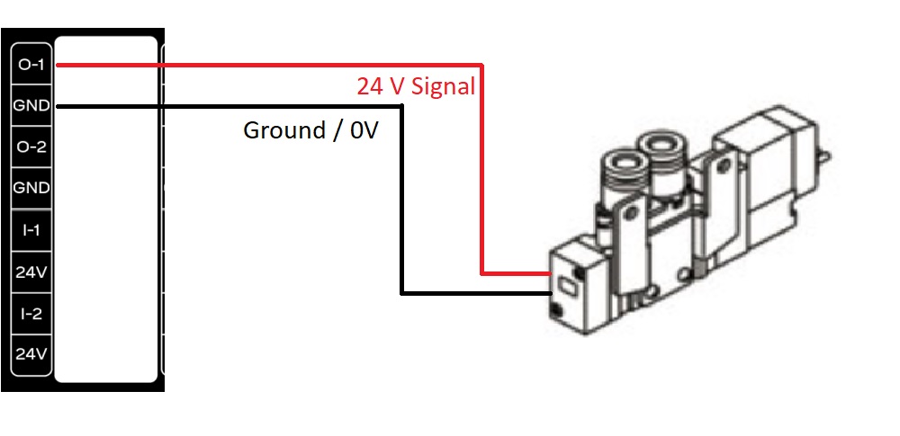
Example of wiring a pneumatic valve into the RO1 control box:
3.8.2 Analog Inputs and Outputs
The RO1 control box has 4 analog outputs and 2 analog inputs available on the control box. These are currently unsupported.
3.8.3 I/O Power Select Feature
The RO1 control box enables users to manage input/output (I/O) functions using its integrated 24V power supply. Alternatively, an external 24V power supply can be used if preferred. The diagrams below illustrate both wiring configurations.
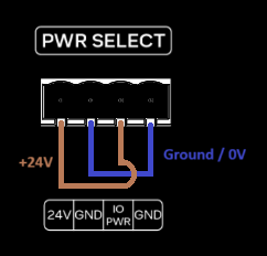
3.8.3.1 Integrated 24V Power Supply
The image below illustrates the wiring configuration for utilizing the integrated 24V power supply for I/O functionality.
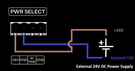
3.8.3.2 External 24V Power Supply
The image below illustrates the wiring configuration for utilizing an external 24V power supply for I/O functionality.
3.9 Marvin Admin Page
The Marvin Admin page allows you to manage and access all of your robots in one location as well as giving you access to useful information. Please note that using the admin page is not necessary for using your robot.
To access the admin page, go to https://marvin.standardbots.com/ in your browser. There you should be able to enter your email address to access your organization’s page. If you are unable to enter your organization’s admin page, please reach out to Standard Bots Support.
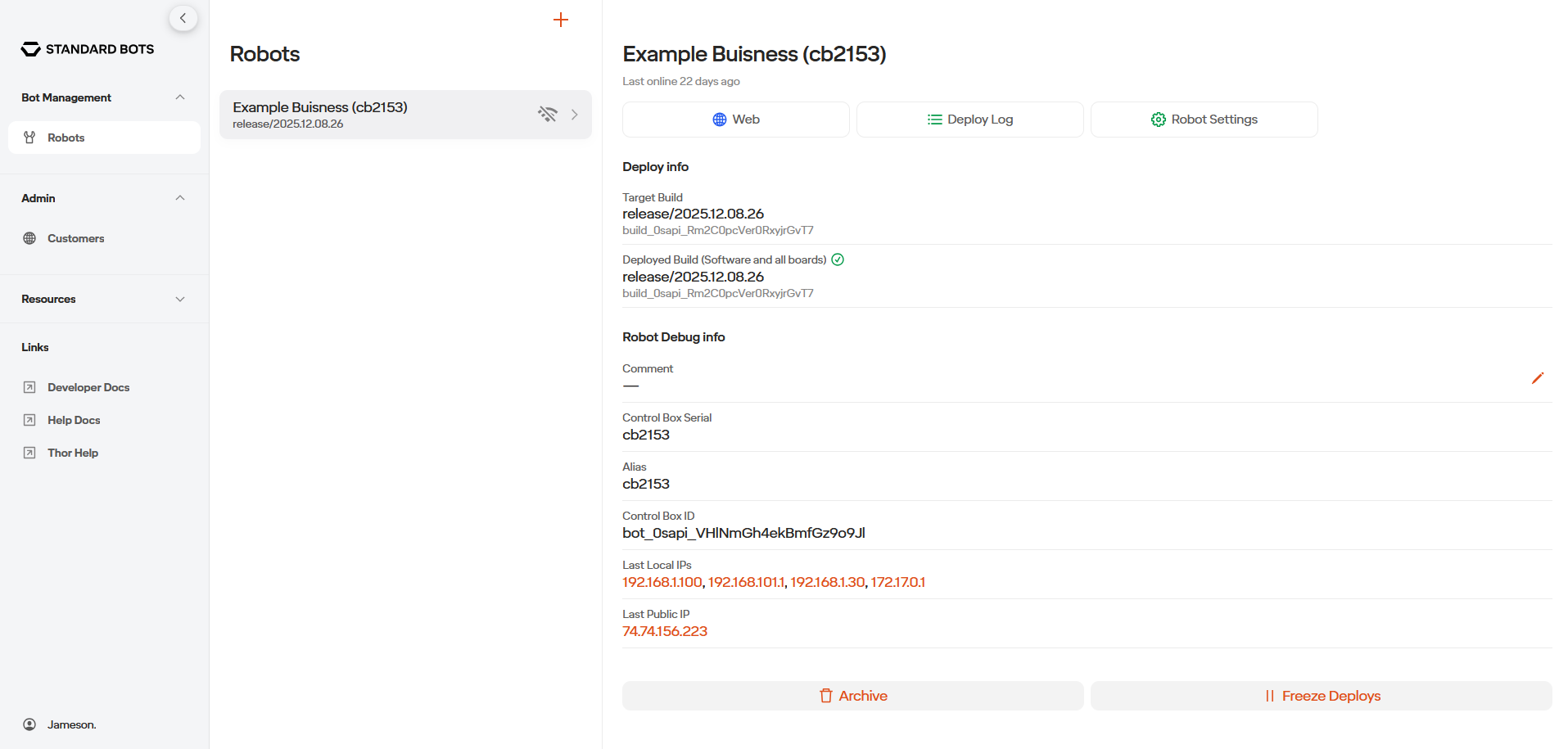
On the Bot Management tab you are able to access the list of robots that you own. Here you can access the robot through the web, see the robot’s installed software version and serial number, and here is where you can create a cloud, simulated, robot.
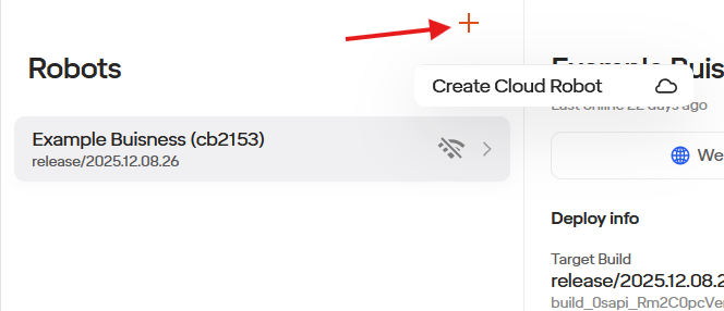
To make a cloud robot, select the orange plus sign at the top of the screen. There you will be able to give the cloud robot a name (which will be used to access your simulated robot on your browser by going to CloudRobotsName.sb.app) and the region. Afterwards you can hit Create. Please note that it does take multiple minutes for the cloud robot to be made. If you experience any issues, please reach out to support.
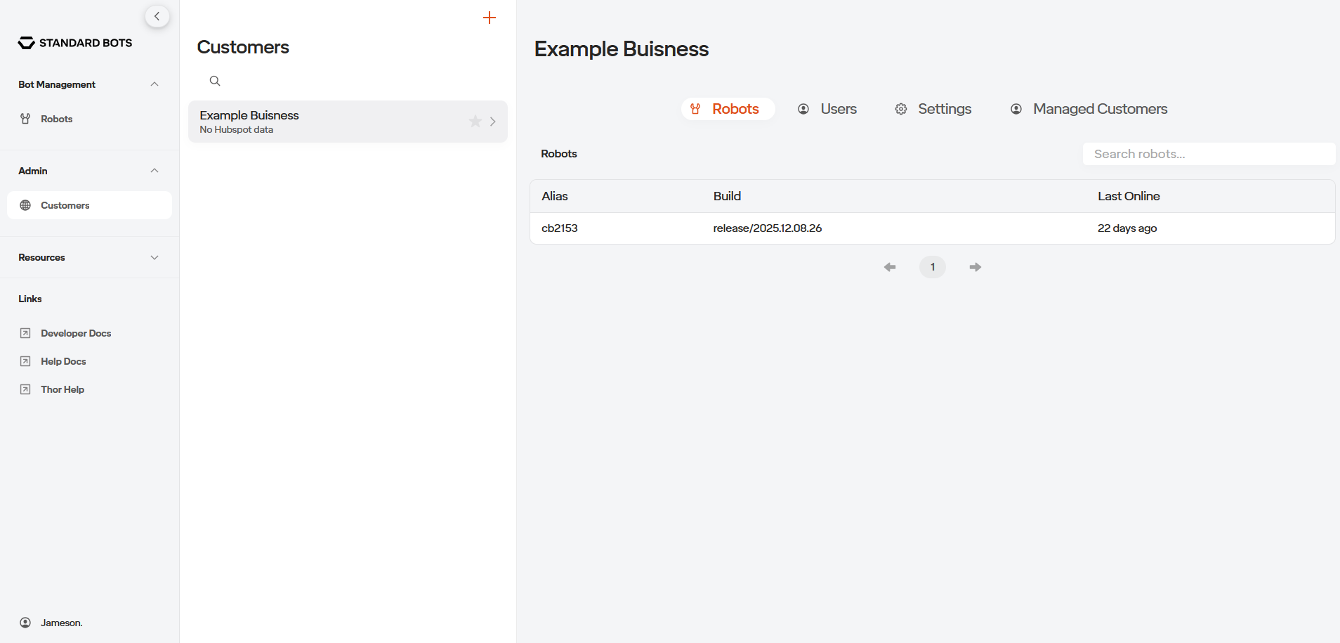
In the Admin Tab you will be able to access your organizations users and robots. Here you can add employees emails to the User’s list which will give them access to your Marvin Admin page. You can also manage your customer’s robots here if applicable.
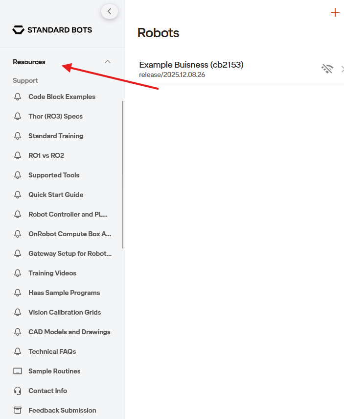
Next is the Resources Tab. Here you have access to useful information such as CAD files, example routines, supported tools, and much more.